RFID systems and methods for optical fiber network deployment and maintenance

a technology of optical fiber network and optical fiber, applied in the direction of burglar alarm mechanical actuation, burglar alarm by hand-portable article removal, instruments, etc., can solve the problems of high error risk, equipment-intensive and labor-intensive undertaking, and the deployment and maintenance of ofns

Inactive Publication Date: 2010-07-20
CORNING CABLE SYST LLC
View PDF380 Cites 52 Cited by
  • Summary
  • Abstract
  • Description
  • Claims
  • Application Information

AI Technical Summary

Benefits of technology

[0109]The automated tracking of OFN components afforded by the present invention reduces the risk of misidentification and errors that often accompany manual updates of an OFN component inventory database. The present invention also provides for faster and more accurate installation, provisioning operations, fault location and maintenance of the OFN.
[0110]It will be apparent to those skilled in the art that various modifications and variations can be made to the present invention without departing from the spirit and scope of the invention. Thus, it is intended that the present invention cover the modifications and variations of this invention provided they come within the scope of the appended claims and their equivalents.

Problems solved by technology

The deployment and maintenance of an OFN is an equipment-intensive and labor-intensive undertaking.
Besides the extra time spent, there is a high risk of errors due to misidentification, database entry errors or failures to correctly update the database.

Method used


Image

  • RFID systems and methods for optical fiber network deployment and maintenance
  • RFID systems and methods for optical fiber network deployment and maintenance
  • RFID systems and methods for optical fiber network deployment and maintenance

Examples


example rfid tag reader

[0063]With continuing reference to FIG. 5, an example embodiment of RFID tag reader 400 includes a receive / transmit antenna 480, a signal processing circuit 482 electrically connected thereto, and a memory unit 484 electrically connected to the signal processing circuit. RFID tag reader 400 also includes other electronic components that not essential to the present invention and so are not shown. In an example embodiment, RFID tag reader 400 includes a GPS circuit 486 adapted to provide GPS data to signal processing circuit 482 and / or to memory unit 484.

[0064]Signal processing circuit 482 is adapted to generate interrogation signal SI and transmit it via antenna 480 to RFID tag Tn as an electromagnetic interrogation signal SI″. Signal processing circuit 482 is also adapted to write information to RFID tag Tn based on information either stored in memory unit 484, entered into the RFID tag reader directly by a user, or communicated to it from database unit 410, as described below.

[006...

example database

Unit

[0066]In an example embodiment, RFID tag reader 400 is operably coupled to database unit 410 so that it can transmit information to and receive information from the database unit. In an example embodiment, database unit 410 includes a second transmit / receive antenna 494 used to wirelessly communicate with RFID tag reader 400, through a Wi-Fi network or through the cellular phone network, as examples. In another example embodiment, database unit 410 is operably coupled to RFID tag reader 400 via a non-wireless (e.g., an electrical or optical) communication link 492, such as an Ethernet link.

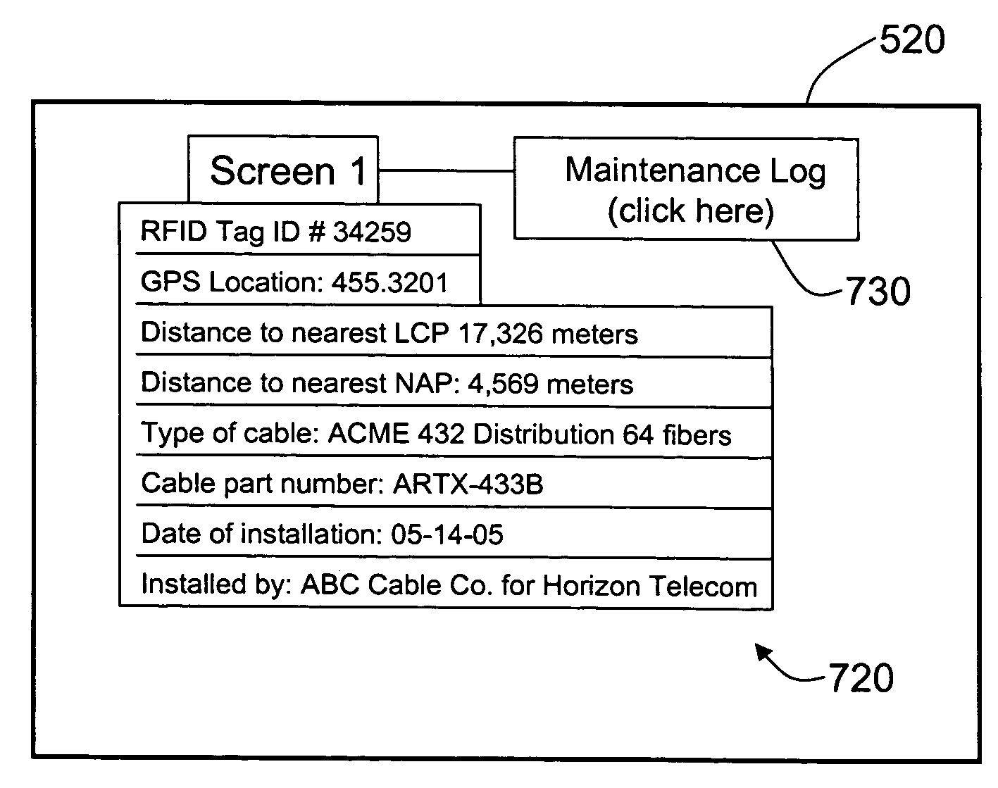
[0067]Database unit 410 includes a microprocessor 500 operably connected thereto, a memory unit 510 operably coupled to the microprocessor, and a display 520 operably coupled to the microprocessor. In an example embodiment, database unit 410 is or otherwise includes a computer, such as a laptop computer, personal computer or workstation. In an example embodiment, database unit 410 is mobile (e...


PUM


Abstract

An optical-fiber-network (OFN) radio-frequency identification (RFID) system for deploying and / or maintaining an OFN. The system includes a plurality of OFN components, and at least one RFID tag that includes RFID tag data that has at least one property of the OFN component associated with the RFID tag. The RFID tag data is written to and read from the RFID tags prior, during or after deploying the OFN components. An OFN-component-data database unit is used to store and process the RFID tag data. This allows for different maps of the OFN to be made, such as an inventory map and a maintenance map. The OFN-RFID system allows for automated operations and management of OFN components by service personnel, and provides for faster and more accurate OFN system deployment and maintenance.

Description

BACKGROUND OF THE INVENTION[0001]1. Field of the Invention[0002]The present invention relates to optical-fiber-based communication systems and networks, and particularly to systems and methods of deploying and maintaining optical fiber networks using radio-frequency identification (RFID) systems and methods.[0003]2. Technical BackgroundOptical Networks[0004]The typical optical fiber network (OFN) includes one or more central offices (COs), one or more remote nodes (RNs) connected to the COs by corresponding optical fiber links, a number of network interface devices (NIDs) coupled to respective RNs by corresponding optical fiber links, and a number of termination points coupled to the NIDs by additional optical fiber links. There are a number of different types of OFNs. One general type of OFN is called an active point-to-point architecture, which includes the Home Run Fiber (HRF) and Active Star Ethernet (ASE). Another general type of OFN is called a passive point-to-multipoint arch...

Claims


Application Information

Patent Timeline
Patent Type & Authority Patents(United States)
IPC IPC(8): G08B13/14
CPCH04L12/66H04Q11/0067H04Q2011/0079H04L41/0806H04L41/0856H04L41/0886H04L43/0811H04L43/0829H04L41/12
Inventor KOZISCHEK, DAVID R.DOWNIE, JOHN D.SUTHERLAND, JAMES S.WAGNER, RICHARD E.TAYLOR, MARK P.WHITING, MATTHEW S.NEDERLOF, LEO
Owner CORNING CABLE SYST LLC
Why Eureka
Try Eureka