Disk drive adjusting head bias during servo synchronization to compensate for over/under sensitivity

Inactive Publication Date: 2010-07-20
WESTERN DIGITAL TECH INC
View PDF39 Cites 134 Cited by
  • Summary
  • Abstract
  • Description
  • Claims
  • Application Information

AI Technical Summary

Problems solved by technology

However, for certain heads the initial nominal bias may be too high or too low causing the head to be over or under sensitive.
As a result, the amplitude of the read

Method used


Image

  • Disk drive adjusting head bias during servo synchronization to compensate for over/under sensitivity
  • Disk drive adjusting head bias during servo synchronization to compensate for over/under sensitivity
  • Disk drive adjusting head bias during servo synchronization to compensate for over/under sensitivity

Examples


Embodiment Construction

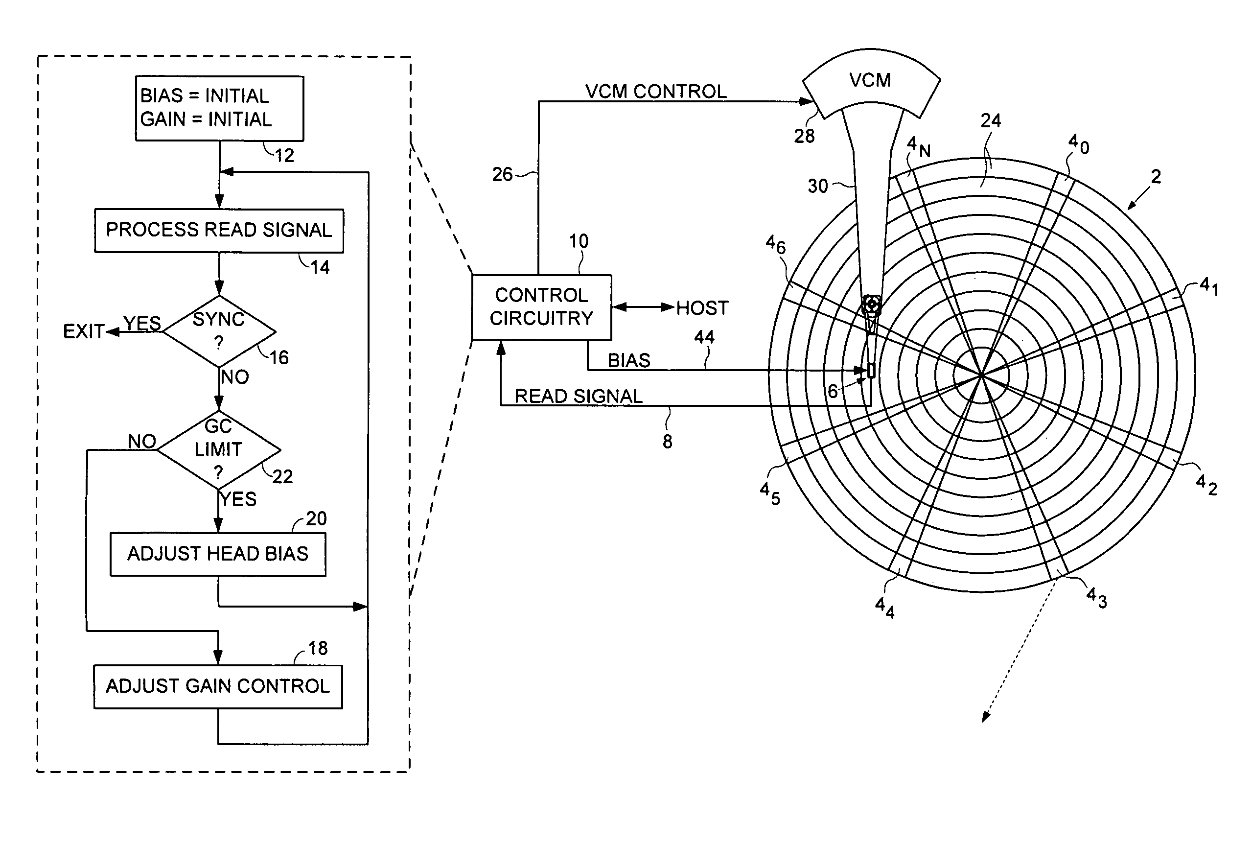
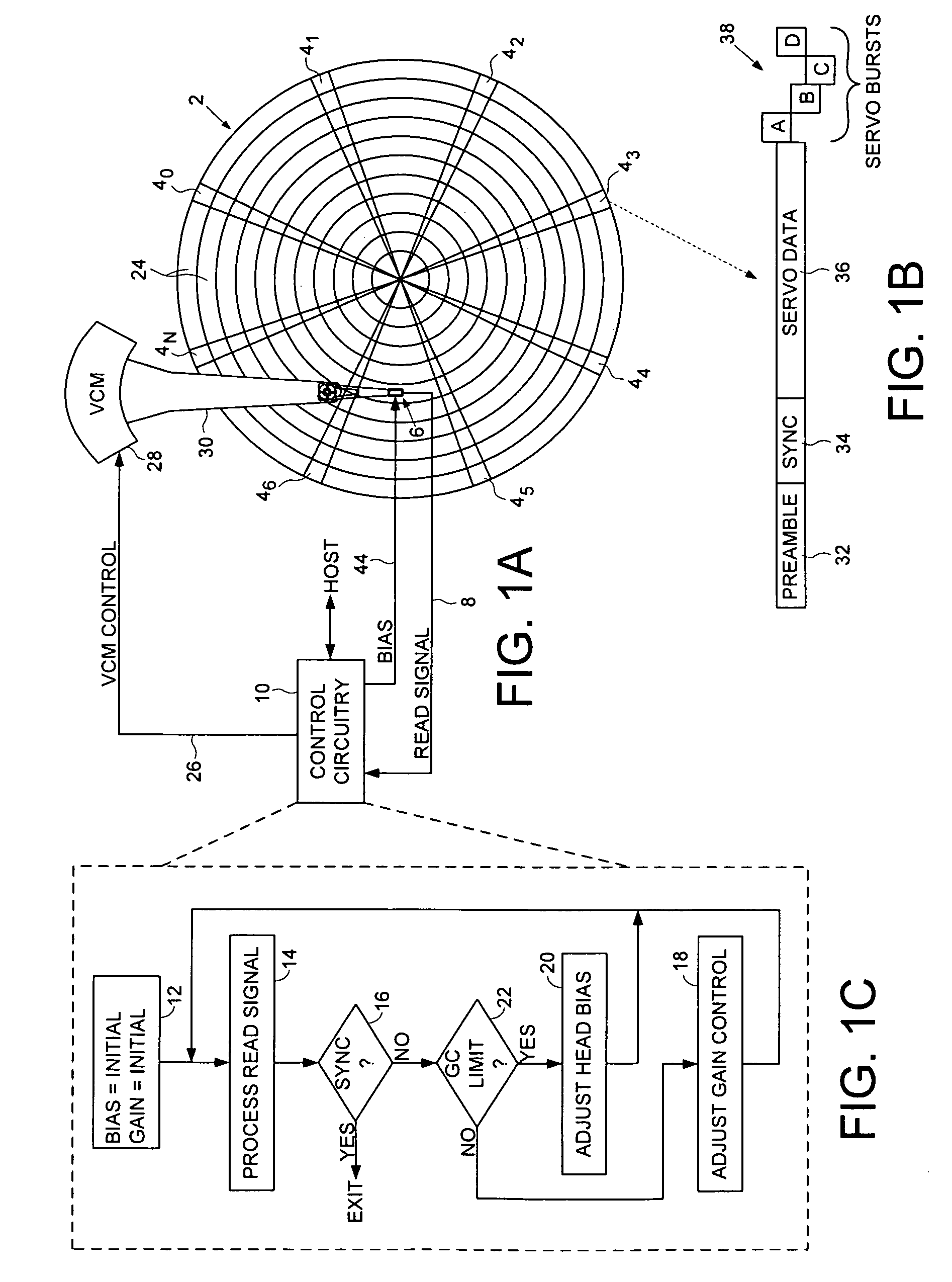
[0010]FIG. 1A shows a disk drive according to an embodiment of the present invention comprising a disk 2 including a plurality of servo sectors 40-4N, a head 6 actuated over the disk 2, the head 6 for generating a read signal 8, and control circuitry 10 including a gain control circuit for adjusting a gain of the read signal 8 in response to a gain setting. The control circuitry 10 executes the flow diagram of FIG. 1C wherein a bias setting is initialized for the head, and the gain setting for the read signal is initialized (step 12). The read signal 8 is processed to detect at least one of the servo sectors (step 14), and when at least one of the servo sectors is not detected (step 16), the gain setting is adjusted (step 18). The read signal is processed with the adjusted gain setting to detect at least one of the servo sectors (step 14), and when at least one of the servo sectors is not detected with the adjusted gain setting (step 16), the bias setting is adjusted in response to ...


PUM


Abstract

A disk drive is disclosed comprising a disk including a plurality of servo sectors, a head actuated over the disk, the head for generating a read signal, and a gain control circuit for adjusting a gain of the read signal in response to a gain setting. A bias setting is initialized for the head, and the gain setting for the read signal is initialized. The read signal is processed to detect at least one of the servo sectors, and when at least one of the servo sectors is not detected, the gain setting is adjusted. The read signal is processed with the adjusted gain setting to detect at least one of the servo sectors, and when at least one of the servo sectors is not detected with the adjusted gain setting, the bias setting is adjusted in response to the adjusted gain setting.

Description

BACKGROUNDDescription of the Related Art[0001]Disk drives comprise a disk and a head connected to a distal end of an actuator arm which is rotated about a pivot by a voice coil motor (VCM) to position the head radially over the disk. The disk comprises a plurality of radially spaced, concentric tracks for recording user data sectors and embedded servo sectors. The embedded servo sectors comprise head positioning information (e.g., a track address) which is read by the head and processed by a servo control system to control the velocity of the actuator arm as it seeks from track to track. When the disk drive is powered on, the control circuitry positions the head over the disk surface and then processes the read signal in order to detect and synchronize to sync marks in the embedded servo sectors. Once synchronized to the servo sectors, the control circuitry is able to identify and track the radial and circumferential location of the head while performing access operations.[0002]Cert...

Claims


Application Information

Patent Timeline
IPC IPC(8): G11B5/03
CPCG11B5/59622G11B5/09G11B2005/0018
Inventor TRINH, TUYEN V.
Owner WESTERN DIGITAL TECH INC
Why Eureka
Try Eureka