Packet acquisition and channel tracking for a wireless communication device configured in a zero intermediate frequency architecture

a wireless communication device and zero intermediate frequency technology, applied in the field of wireless communication, can solve the problems of limited location of each device, many limitations, and difficult implementation, and achieve the effect of convenient implementation

Inactive Publication Date: 2006-06-27
INTELLECTUAL VENTURES I LLC
View PDF29 Cites 41 Cited by
  • Summary
  • Abstract
  • Description
  • Claims
  • Application Information

AI Technical Summary

Benefits of technology

[0018]When the DC threshold condition is exceeded, the method includes operating the DC feedback control loop by adding DC to the receive signal. Several methods are contemplated, including conducting a step search procedure by repeatedly adding a predetermined DC amount until the DC threshold condition is met. The predetermined DC amount may be any arbitrary value, but should be selected to avoid overshooting the gain window and thus may be related to the relative size of the measurement window. In an alternative embodiment, the method includes performing a successive approximation DC search procedure until the DC threshold condition is met. In this case, a binary search or the like is performed to converge on the applicable DC level. The step search procedure may take longer than the successive approximation technique in many cases, but is sufficient, simple, and relatively easy to implement.

Problems solved by technology

Wired networks provide a certain level of convenience but have many limitations.
The location of each device, therefore, is limited to enable access to the network wires.
Cable management is also a significant issue, since devices must be placed to enable proper routing of wires.
Once wired devices are properly placed, movement of the devices is very limited or otherwise not practical without substantial re-configuration or re-routing of the wires.
Maintenance of wired network devices can be inconvenient and often requires that the wires be removed during service and then reconnected properly.
For network applications, infrared technology is a relatively inexpensive option but has certain limitations, including limited bandwidth, range limitations, and line-of-sight issues.
Due to line of sight issues, infrared technology is not particularly convenient for network communications at the end points of the network where human interaction is necessary.
RF technology for LAN systems, however, is not particularly optimized for small office or home use.
The wireless embodiments for commercial and industrial applications are too expensive or otherwise specialized and thus are not suited for direct use in the small office or home environment.
The Bluetooth technology, however, has limited bandwidth and therefore relatively low data throughput capability.
The typical environment for a WLAN is very noisy and not optimal for wireless communications.
For example, most homes include many electronic devices resulting in an electronically noisy environment that may interfere with WLAN communications, such as microwave ovens, garage door openers, radios, television sets, computer systems, etc.
Further, the communication medium between wireless devices constantly changes.
For example, most environments or rooms include multiple reflective surfaces creating multipath noise in the wireless environment.
Furthermore, movement of items or devices or the like such as hands, bodies, jewelry, mouse pointers, etc. or activation of electronic devices, such as cooling fans or the like, affects the overall wireless communication path and potentially degrades wireless communication performance.

Method used


Image

  • Packet acquisition and channel tracking for a wireless communication device configured in a zero intermediate frequency architecture
  • Packet acquisition and channel tracking for a wireless communication device configured in a zero intermediate frequency architecture
  • Packet acquisition and channel tracking for a wireless communication device configured in a zero intermediate frequency architecture

Examples


Embodiment Construction

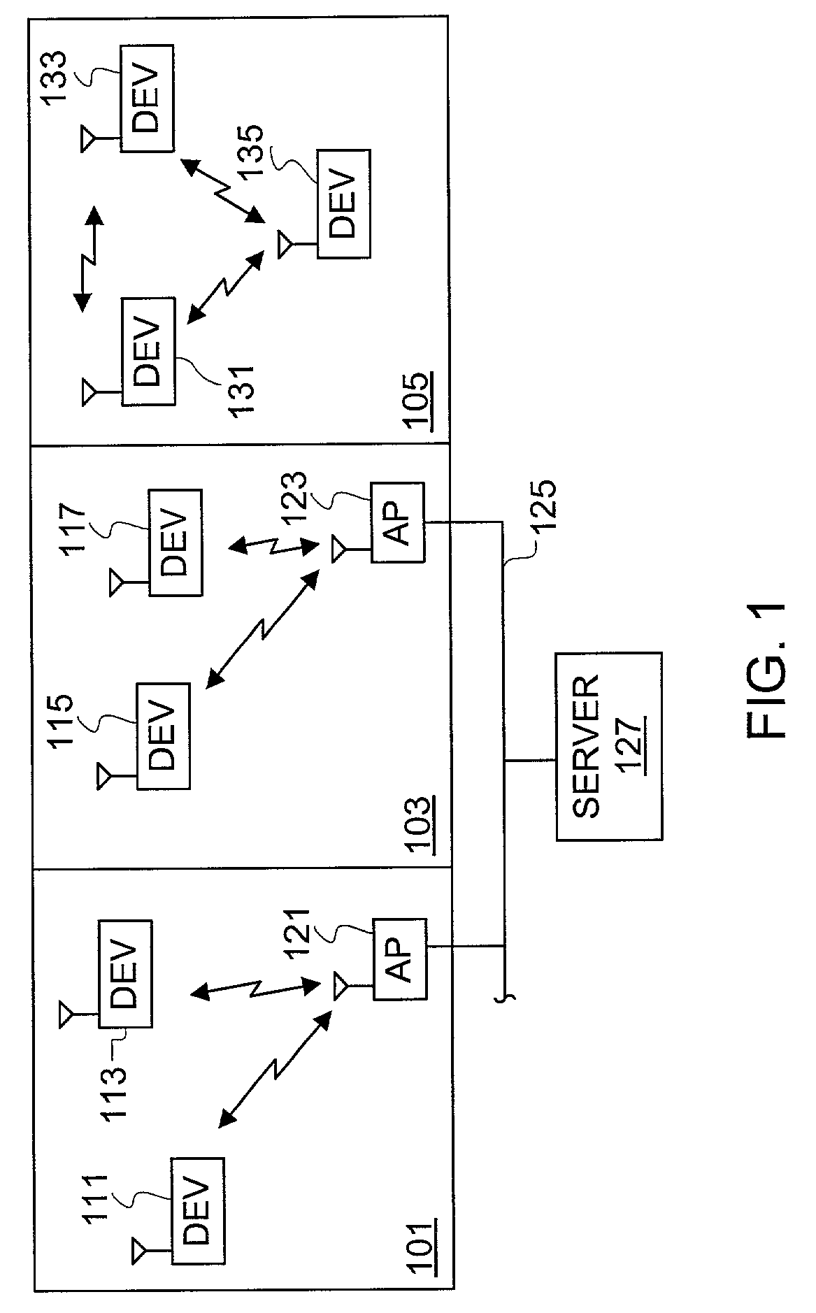
[0034]FIG. 1 is a block diagram of one or more WLANs generally illustrating operation of wireless devices implemented according to one or more embodiments of the present invention. Although the present invention is illustrated for use with WLANs in exemplary embodiments, it is understood that the present invention applies for any radio or wireless communications and is not limited to WLAN applications. A first area 101 and a second area 103 represent separate compartments or divisions of a location such as offices within an office building or rooms within a house. The areas 101 and 103 may each include wireless access points (APs) 121 and 123 for controlling communications within the respective areas 101 and 103. As shown, the APs 121, 123 are coupled to a wired network such as a LAN 125, which is further coupled to a common server computer 127.

[0035]Within the area 101, wireless devices 111 and 113 are able to communicate with each other via the AP 121, and within the area 103, wir...


PUM


Abstract

A method of controlling operation of a wireless device configured in a zero intermediate frequency architecture including a DC loop and a gain loop. The method includes processing energy in a wireless medium to generate a corresponding receive signal, monitoring the receive signal via a predetermined measurement window, detecting a changed condition in the channel, holding the gain feedback control loop at a constant gain level, and operating the DC loop in an attempt to search a stable DC value for the receive signal while the gain loop is held constant. A first case is DC saturation, where the gain is held constant until DC is controlled. A second case is clear channel assessment, where a prior stored gain setting is applied to the gain loop after detecting the end of the packet. A third case is preparation for receiving an expected acknowledgement packet after transmitting a packet, where again a prior stored gain setting is applied to the gain loop and DC is searched.

Description

CROSS-REFERENCE TO RELATED APPLICATION(S)[0001]The present application is based on U.S. Provisional Patent Application entitled “Packet Acquisition and Channel Tracking For A Wireless Communication Device Configured In A Zero Intermediate Frequency Architecture”, Ser. No. 60 / 259,731, filed Jan. 4, 2001, which is hereby incorporated by reference in its entirety. The present application is also a continuation-in-part (CIP) of U.S. Patent Application entitled “A Calibrated DC Compensation System For A Wireless Communication Device Configured In A Zero Intermediate Frequency Architecture”, Ser. No. 09 / 677,975, filed Oct. 2, 2000, which is hereby incorporated by reference in its entirety.FIELD OF THE INVENTION[0002]The present invention relates to wireless communications, and more particularly to packet acquisition and channel tracking for a wireless communication device configured in a zero intermediate frequency (ZIF) architecture that utilizes a DC control loop to enable direct conver...

Claims


Application Information

Patent Timeline
Patent Type & Authority Patents(United States)
IPC IPC(8): H04B1/06H04B7/00H03G3/30H03D3/00H04B1/16H04B1/30H04L25/06
CPCH03D3/008H03L7/0812H04L25/061H04B1/30H03L7/085
Inventor BALDWIN, KEITH R.WEBSTER, MARK A.
Owner INTELLECTUAL VENTURES I LLC
Why Eureka
Try Eureka