Image pickup apparatus and lens barrel

a technology of image pickup and lens barrel, which is applied in the direction of exposure control, optical radiation measurement, printers, etc., can solve the problems of object shake, image quality degradation, and image quality degradation of photographed images, so as to prevent the increase of the photographing sensitivity, reduce the degradation of image quality, and improve the effect of image quality

Inactive Publication Date: 2008-08-28
PANASONIC CORP
View PDF39 Cites 40 Cited by
  • Summary
  • Abstract
  • Description
  • Claims
  • Application Information

AI Technical Summary

Benefits of technology

[0016]It is therefore an object of the present invention to provide an imaging apparatus and lens barrel that reduce image quality degradation due to camera shake and object shake by preventing photographing sensitivity from being increased more than necessary and enabling images in good quality to be photographed.
[0018]According to another aspect of the present invention, an imaging apparatus body is used in combination with a lens barrel mounted with a camera shake correcting section that corrects shake of an optical image caused by motion of the imaging apparatus body, the imaging apparatus body having: an imaging sensor that receives a formed optical image, converts the optical image to an electrical image signal and outputs the image signal; a face detection section that detects a face of a photographing object based on the image signal; an object speed decision section that measures motion of the optical image of the face of the photographing object in a predetermined time before a photograph is taken, and calculates an object speed of the photographing object; and a control section that takes, when the calculated object speed is equal to or higher than a threshold, a photograph at a higher amplification factor of the image signal and in a shorter exposure time.

Problems solved by technology

However, accompanying reductions in size and weight and escalation in the magnification of optical zooming of digital cameras, a blur may occur in photographed images and may cause image quality degradation.
On the other hand, among causes for degrading image quality of photographed images is object shake caused by the motion of the photographing object, in addition to camera shake caused by vibration such as caused by a shaking hand, added to the camera.
Generally, when photographing sensitivity is increased, the output signal from the imaging sensor is amplified, and, consequently, noise generated from the imaging sensor is also amplified.
Therefore, an image taken in high sensitivity contains a large amount of noise.
Increasing photographing sensitivity more than necessary may thus result in image quality degradation.
However, with such a conventional imaging apparatus, it is difficult for photographers to identify what level of moving speed of the photographing object causes object shake.
Therefore, cases often occur where even though it is possible to take a photograph without object shake, the photographer observing the motion of the photographing object misjudges that object shake will occur.
As a result, there is a problem that the photographers change photographing sensitivity to high sensitivity and take a photograph containing a large amount of noise.
Furthermore, there is a problem that photographers need to change photographing sensitivity immediately before taking a photograph and might miss the chance to take a photograph.
That is, a general photographer cannot identify what level of moving speed of the photographing object will or will not cause object shake.
In other words, using the camera shake correcting function may result in taking a photograph with object shake when the photographing object is moving fast, and increasing ISO sensitivity may result in taking a photograph with a large amount of noise when the photographing object is moving slowly.
Therefore, taking photographs in good quality is not possible.
Furthermore, although the digital camera having a blur correcting optical system disclosed in Patent Document 1 can reduce image quality degradation due to camera shake, there is no proposal of easing image quality degradation caused by object shake.
Furthermore, since the digital camera disclosed in Patent Document 2 is only directed to predicting the motion of the photographing object and is not directed to deciding what level of moving speed of the photographing object will or will not cause object shake, it is not always possible to take a photograph at an optimal shutter speed matching the speed of the photographing object.

Method used


Image

  • Image pickup apparatus and lens barrel
  • Image pickup apparatus and lens barrel
  • Image pickup apparatus and lens barrel

Examples


embodiment 1

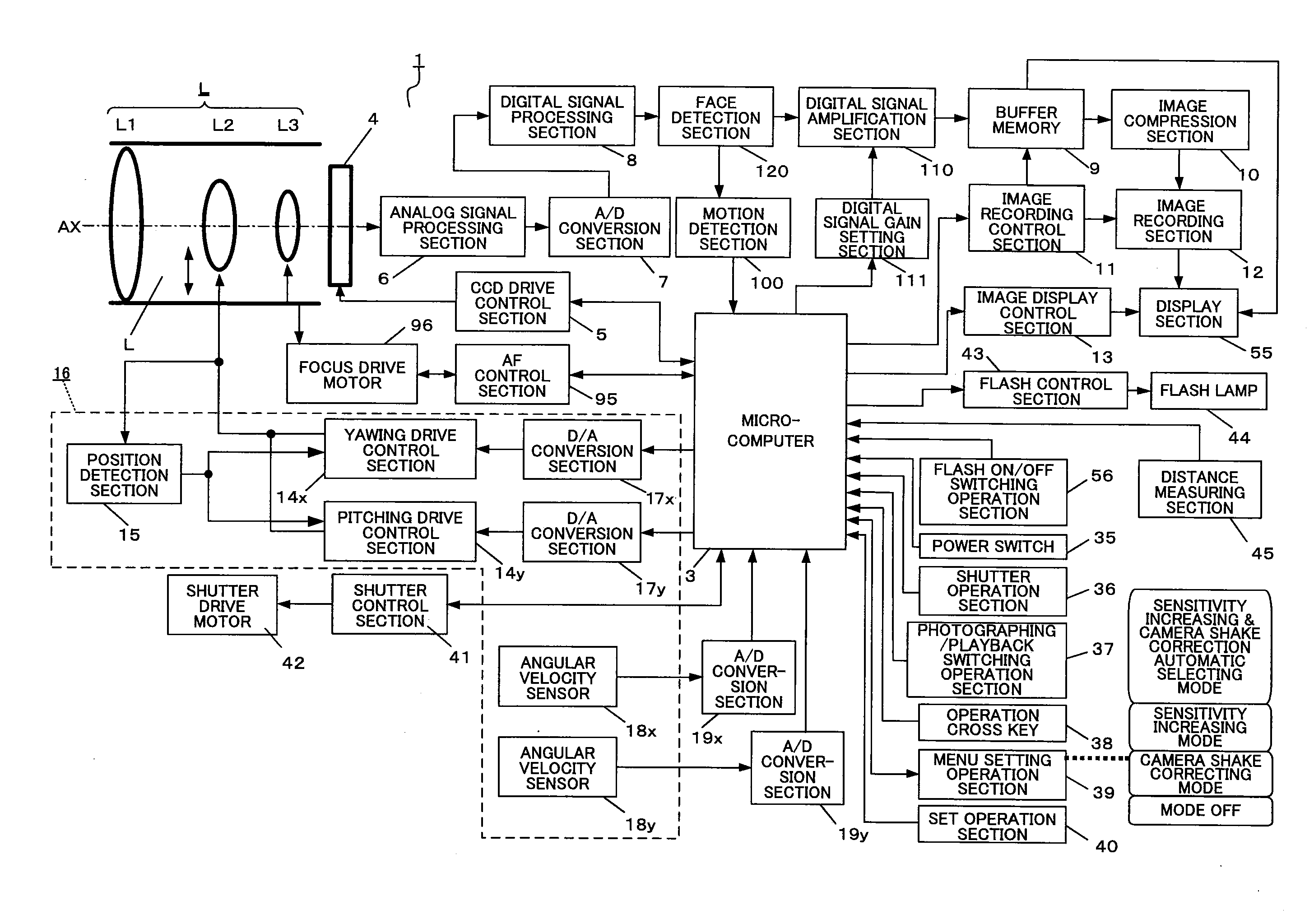
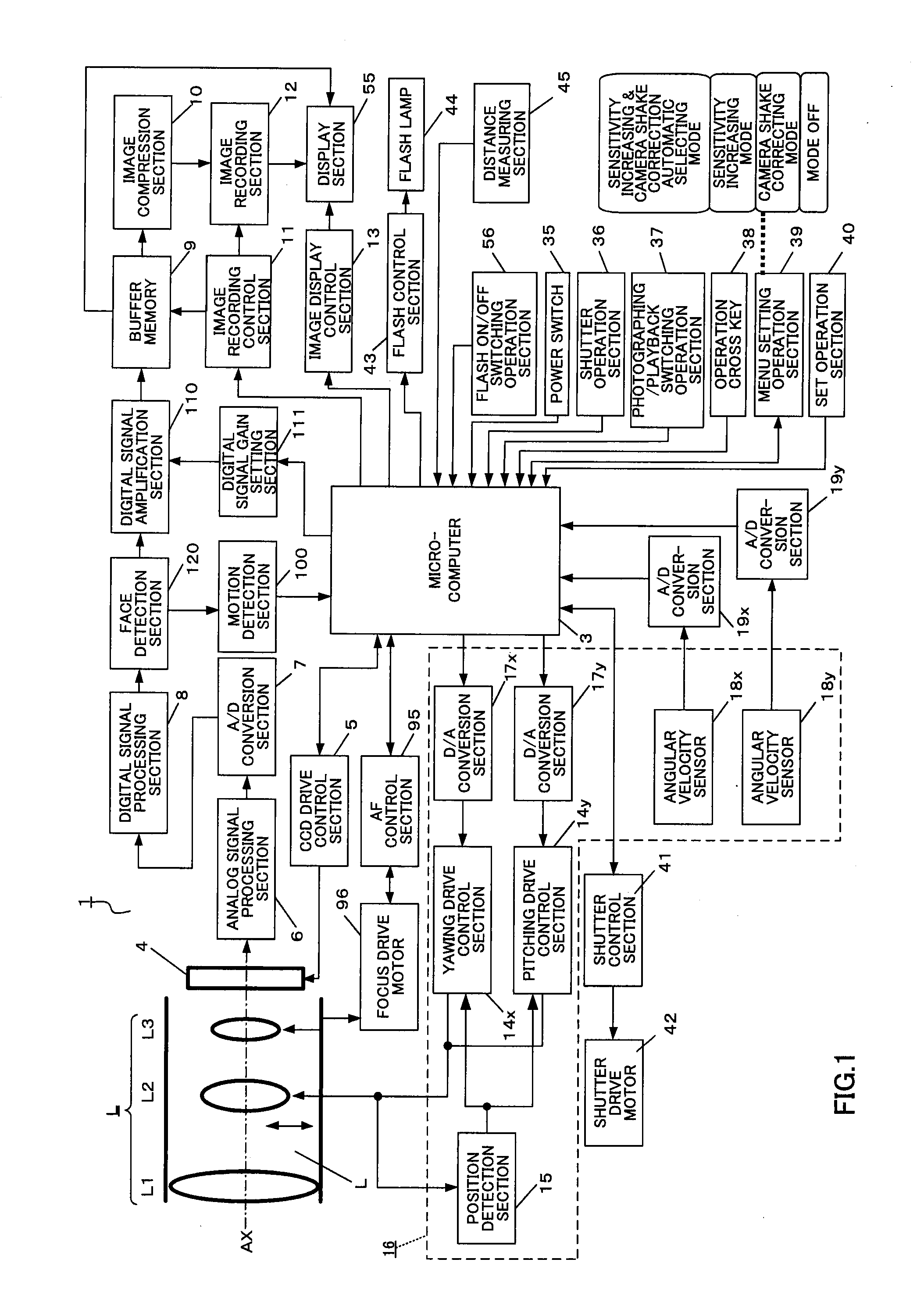
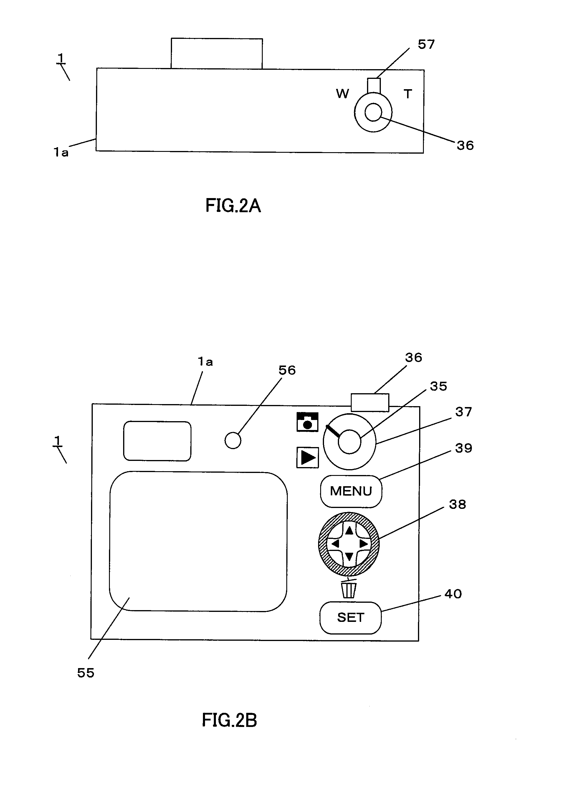
[0032]FIG. 1 is a block diagram showing the configuration of an imaging apparatus according to an embodiment of the present invention. FIG. 2 shows a schematic configuration of the imaging apparatus according to the present embodiment, where FIG. 2A shows a top view and FIG. 2B shows a rear view. The present embodiment is an example of a digital camera application with a camera shake correcting function and a photographing sensitivity changing function. In the following explanation, the moving speed of the photographing object (also referred to as “the object speed”) is the moving speed of an optical image of the photographing object in the imaging plane, caused by one of or both of camera shake and object shake.

[0033]In FIG. 1, digital camera 1 employs a configuration having an imaging optical system L, microcomputer 3, imaging sensor 4, CCD (Charge Coupled Device) drive control section 5, analog signal processing section 6, A / D conversion section 7, digital signal processing secti...

embodiment 2

[0115]A case will be explained below with Embodiment 2 where the motion of the faces of a plurality of photographing objects are detected and the photographing mode is set.

[0116]The hardware configuration of the imaging apparatus according to Embodiment 2 of the present invention is substantially the same as shown in FIGS. 1 to 3, and so the explanations will be omitted.

[0117]The digital camera according to the present embodiment differs from the digital camera according to Embodiment 1 in making possible selecting an arbitrary photographing object from a plurality of photographing objects, detecting the motion of the face of the selected photographing object and selecting a photographing mode. The same components as in Embodiment 1 will be assigned the same reference numerals and explanations will be focused upon points different from Embodiment 1.

[0118]FIG. 10 shows a display example where how face detection is carried out for a plurality of children is displayed on display sectio...


PUM


Abstract

An imaging apparatus capable of preventing photographing sensitivity from being increased more than necessary, reducing image quality degradation caused by camera shake or object shake and easily photographing images in good image quality. Digital camera 1 includes image shake correcting selection 16 that corrects shake of an optical image of a photographing object formed by an imaging optical system L, digital signal amplification section 110 that amplifies an image signal with a gain set by digital signal gain setting section 111, and face detection section 120 that detects a face of a photographing object, and microcomputer 3 calculates an object speed based on the detected motion of the face of the photographing object, decides whether or not the object speed is equal to or higher than a threshold A, and operates, when the object speed is lower than the threshold A, image shake correction by controlling image shake correcting section 16 or increases, when the object speed is equal to or higher than the threshold A, the gain of digital signal gain setting section 111, increases ISO sensitivity to increase the shutter speed and shorten the exposure time.

Description

CROSS REFERENCE TO RELATED APPLICATIONS[0001]The disclosure of Japanese Patent Application No. 2007-042065, filed on Feb. 22, 2007, including the specification, drawings and abstract, is incorporated herein by reference in its entirety.BACKGROUND OF THE INVENTION[0002]1. Field of the Invention[0003]The present invention relates to an imaging apparatus and lens barrel. More particularly, the present invention relates to an imaging apparatus and lens barrel having a camera shake correcting function and a photographing sensitivity changing function.[0004]2. Description of Related Art[0005]Imaging apparatuses such as digital still cameras and digital video cameras that convert an optical image of a photographing object to an electrical image signal and outputs the image signal (hereinafter simply referred to as “digital cameras”), have become popular. With reductions in size and weight and escalation in the magnification of optical zooming in recent years in particular, digital cameras ...

Claims


Application Information

Patent Timeline
Patent Type & Authority Applications(United States)
IPC IPC(8): H04N5/228G03B5/00G03B7/08G03B7/093G03B7/28H04N5/225H04N5/232
CPCH04N5/23219H04N5/23248H04N5/23254H04N5/243H04N5/23287H04N5/2353H04N5/2327H04N23/611H04N23/6811H04N23/68H04N23/684H04N23/687H04N23/73H04N23/76
Inventor YUMIKI, NAOTO
Owner PANASONIC CORP
Why Eureka
Try Eureka