Packet tracing using dynamic packet filters

a dynamic packet and packet filter technology, applied in the field of tracing ip packets, can solve the problems of not providing an accurate measurement of real traffic round trip delay, no guarantee that return traffic takes a reciprocal route, and difficult to answer

Active Publication Date: 2010-07-20
VIAVI SOLUTIONS INC
View PDF11 Cites 14 Cited by
  • Summary
  • Abstract
  • Description
  • Claims
  • Application Information

AI Technical Summary

Problems solved by technology

This routing poses a question which is simple to ask, but difficult to answer: what path does a packet take through the network?
Additionally, the path is only traced in a single direc

Method used


Image

  • Packet tracing using dynamic packet filters
  • Packet tracing using dynamic packet filters
  • Packet tracing using dynamic packet filters

Examples


Embodiment Construction

[0013]The invention relates to packet tracing in packet-based networks. The following description is presented to enable one skilled in the art to make and use the invention, and is provided in the context of a patent application and its requirements. Various modifications to the disclosed embodiments will be readily apparent to those skilled in the art, and the generic principles herein may be applied to other embodiments. Thus, the invention is not intended to be limited to the embodiments show but is to be accorded the widest scope consistent with the appended claims and with the principles and features described herein.

[0014]With reference now to the figures and in particular with reference to FIGS. 1 through 3, representative embodiments of the invention are shown.

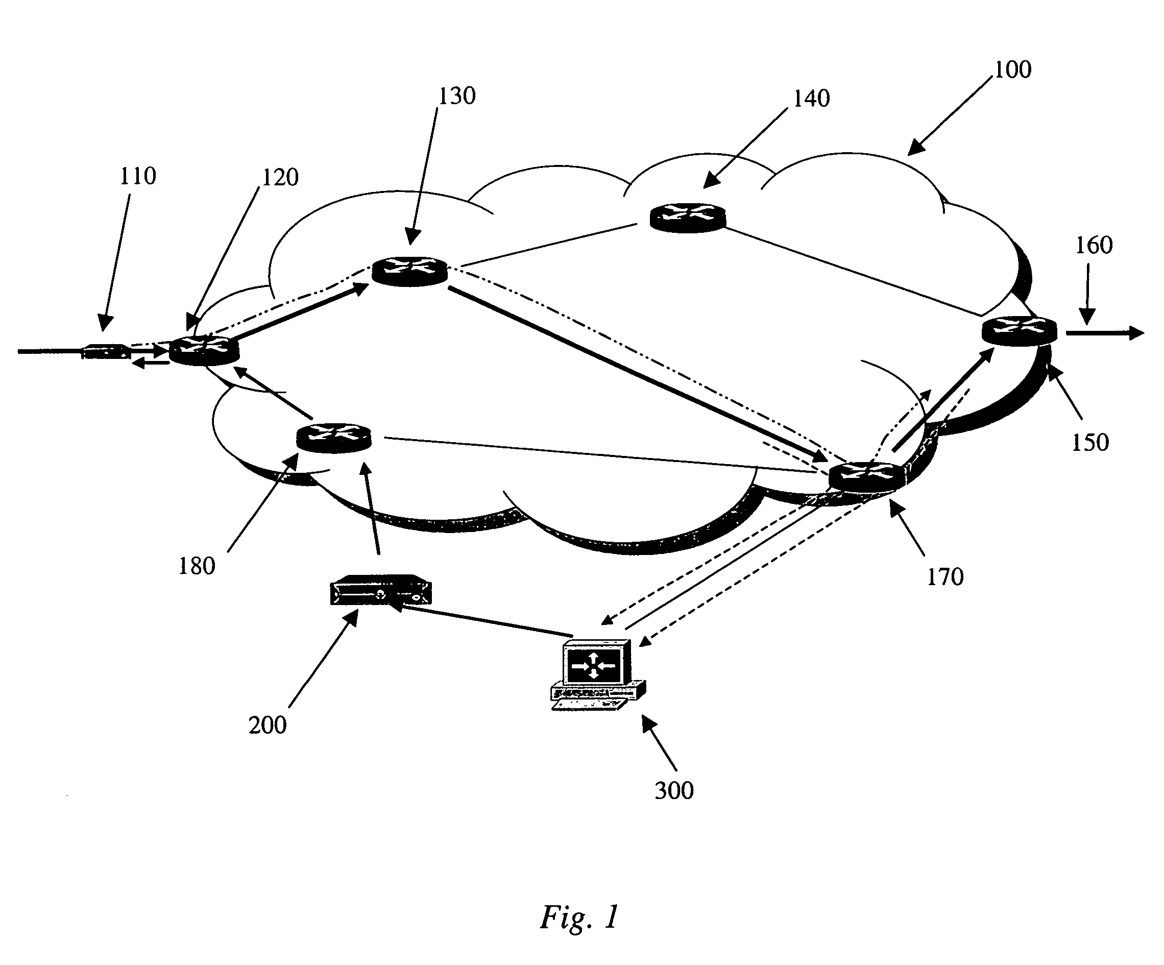
[0015]FIG. 1 shows network 100 with routers 120, 130, 140, 150, 170, and 180. As shown, multiple paths exist between starting point 110 and exit path 160.

[0016]Packet tracing according to the present invention takes p...


PUM


Abstract

Packet tracing in switched packet networks. Tracing of live packet data in a network is performed by discovering the measurement path, setting up dynamic filters along the path to collect traffic information, and collecting data as detected by the dynamic filters. Collected data is sent to a measuring entity. Filter setup may be repeated to capture data as routing changes.

Description

TECHNICAL FIELD[0001]Embodiments in accordance with the invention relate generally to tracing IP packets through digital networks.BACKGROUND[0002]Modern digital networks are IP networks, based on packet-switched Internet Protocols. Packets of information travel from a source node connected to the network to a destination node connected to the network. The path these packets take through the myriad of possible routes through the network is chosen by routers, and may change. The path between source and destination may not be the same for each packet, and may not be the same in each direction.[0003]This routing poses a question which is simple to ask, but difficult to answer: what path does a packet take through the network?[0004]Tracing a path of IP packets through the network is generally accomplished by using the well-known traceroute utility. Traceroute attempts to report the route or path (the set of IP addresses of router interfaces) through which a certain type of packet (a UDP ...

Claims


Application Information

Patent Timeline
IPC IPC(8): H04L12/28H04L12/56H04L12/24H04L12/26
CPCH04L43/10
Inventor ILNICKI, SLAWOMIR K.TATMAN, LANCE A.
Owner VIAVI SOLUTIONS INC
Why Eureka
Try Eureka