Check valve

a check valve and valve body technology, applied in the field of check valves, can solve the problems of complex devices susceptible to damage, malfunction, leakage, etc., and achieve the effect of maximizing the durability of the check valve and minimizing the complexity of the check valve structur

Inactive Publication Date: 2010-07-27
SUPERB INDS
View PDF14 Cites 5 Cited by
  • Summary
  • Abstract
  • Description
  • Claims
  • Application Information

AI Technical Summary

Benefits of technology

[0006]Harmonious with the present invention, a check valve wherein a complexity of the structure of the check valve is minimized and a durability of the check valve is maximized, has surprisingly been discovered.

Problems solved by technology

Many known check valves are produced from numerous parts resulting in complex devices susceptible to damage, malfunction, and leaks.

Method used


Image

  • Check valve
  • Check valve
  • Check valve

Examples


Embodiment Construction

[0018]The following detailed description and appended drawings describe and illustrate various exemplary embodiments of the invention. The description and drawings serve to enable one skilled in the art to make and use the invention, and are not intended to limit the scope of the invention in any manner. It is understood that materials and uses other than those described can be used without departing from the scope and spirit of the invention.

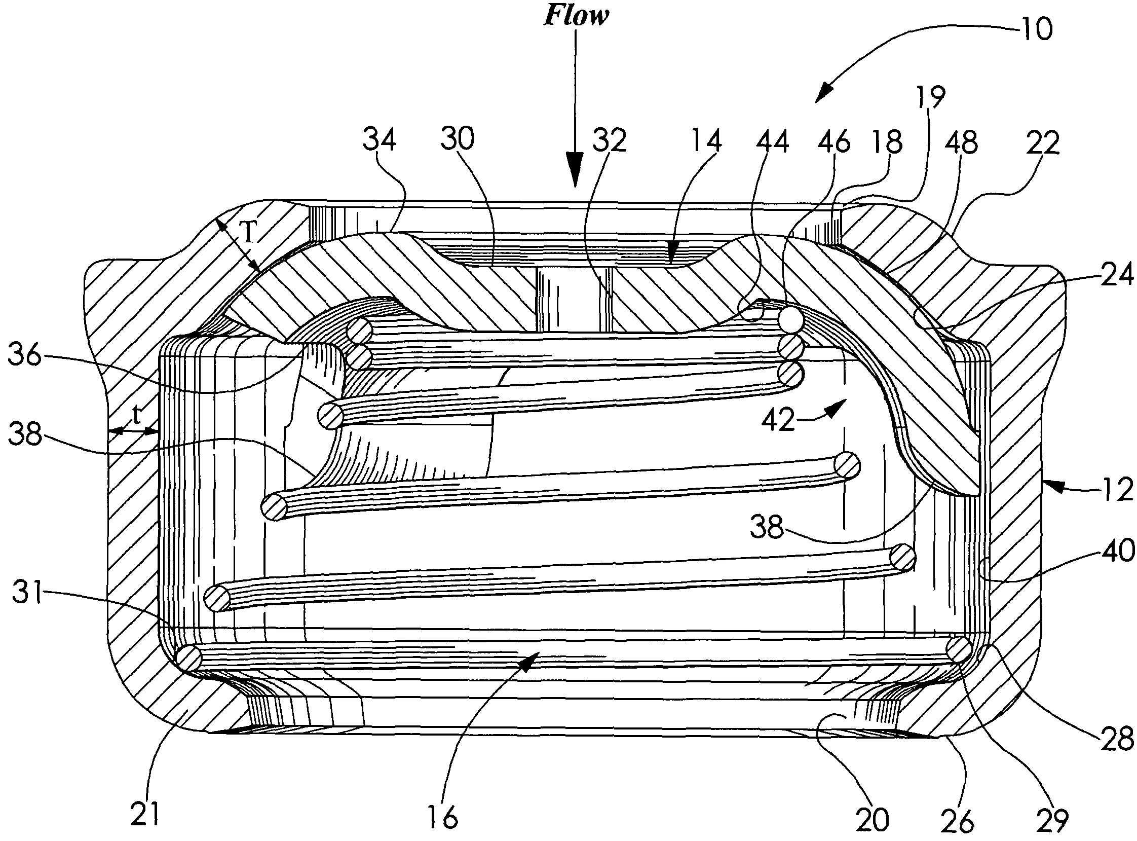
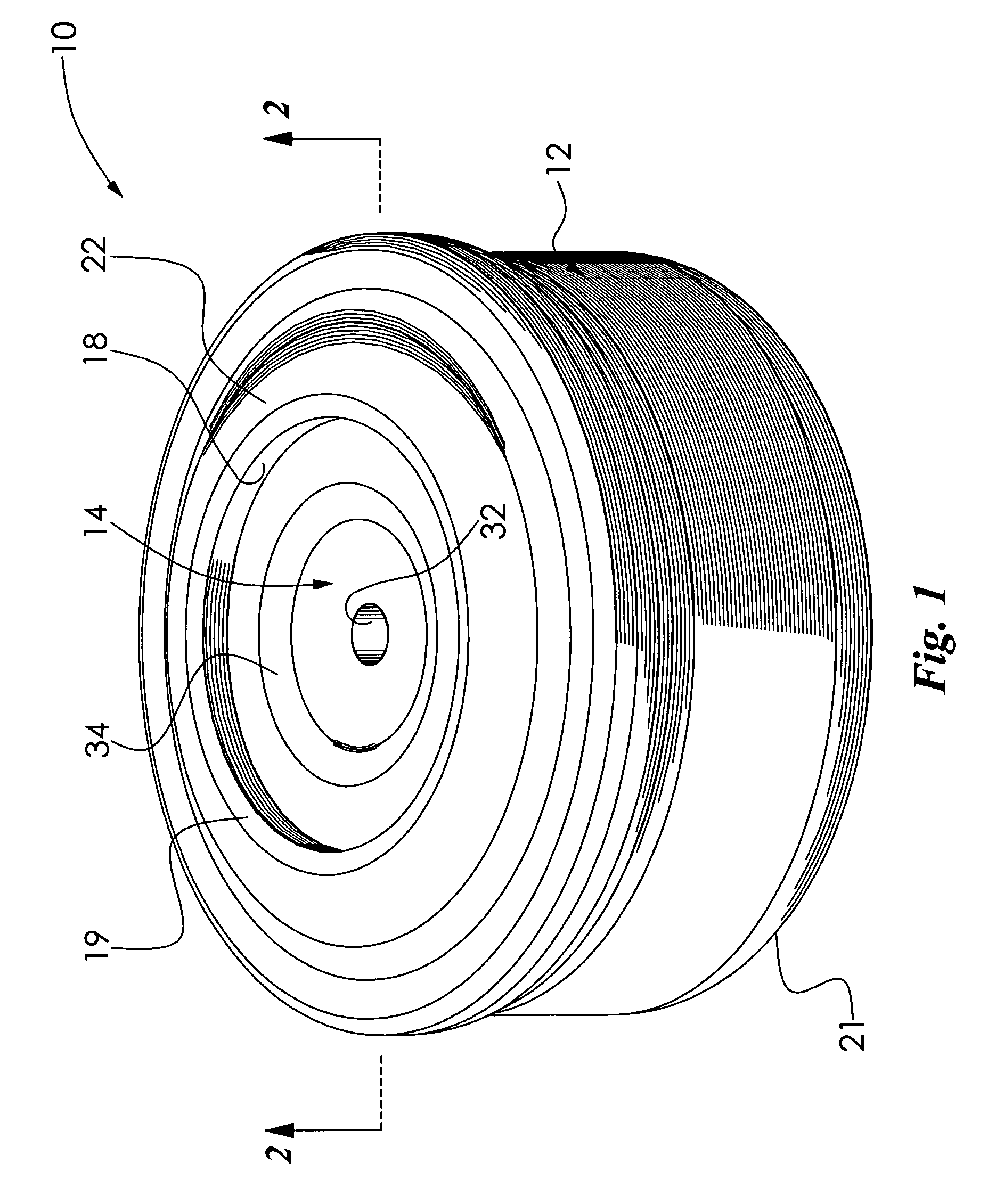
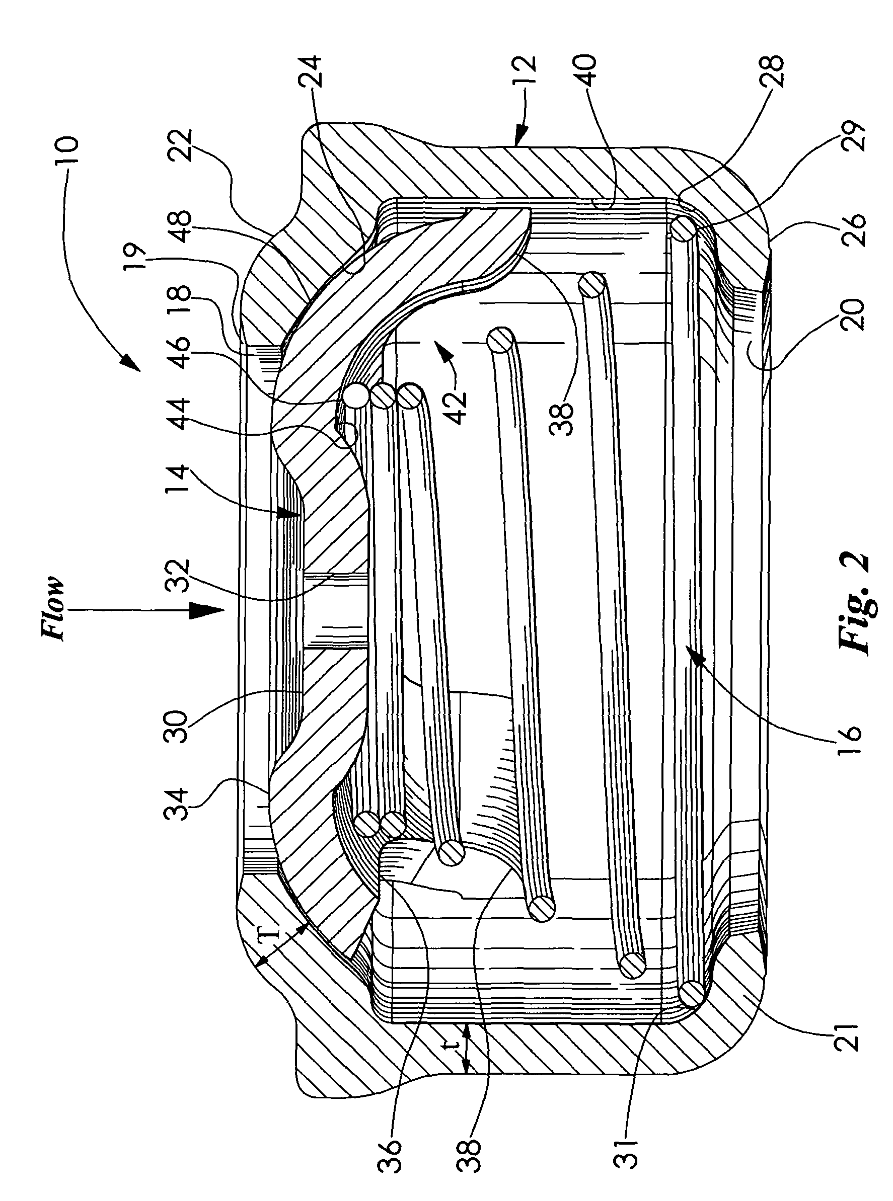
[0019]FIG. 1 illustrates a check valve 10 according to an embodiment of the invention. The check valve 10 includes a hollow main body 12, a poppet valve 14, and an urging member 16 illustrated in FIGS. 2 and 6. The main body 12 has a first aperture 18 formed in a first end 19 thereof and a second aperture 20 formed in a second end 21 thereof, as more clearly shown in FIGS. 2 and 3. A radially inwardly extending first end wall 22 forms the first aperture 18 of the main body 12. A concaved seating surface 24 is formed on an inner surface of the f...


PUM


Abstract

A check valve for a fluid handling system is disclosed, the check valve having a main body with a poppet valve disposed therein and a spring urging the poppet valve into abutment with an inner surface of the main body, wherein the check valve facilitates a flow of fluid in one direction and militates against the flow of fluid in an opposite direction.

Description

CROSS-REFERENCE TO RELATED APPLICATION[0001]This application claims the benefit of U.S. Provisional Patent Application Ser. No. 60 / 694,769 filed on Jun. 28, 2005.FIELD OF THE INVENTION[0002]The invention relates to a check valve and more particularly to a check valve for a fluid handling system, the check valve having a main body with a poppet valve disposed therein and a spring urging the poppet valve into abutment with an inner surface of the main body.BACKGROUND OF THE INVENTION[0003]In fluid handling systems such as fluid transfer systems and hydraulic power systems, for example, it is often necessary to control the direction, amount, and type of flow of the fluid through the system. Various pumps, valves, and other fittings are typically used to provide such control.[0004]A check valve is used in a fluid system to control the direction of flow of the fluid in the fluid system. The fluid can be permitted to flow through the valve only in one direction, wherein the check valve mi...

Claims


Application Information

Patent Timeline
Patent Type & Authority Patents(United States)
IPC IPC(8): F16K15/02
CPCF16K15/026F16K15/028F16K21/02Y10T137/7847Y10T137/7929Y10T137/7938
Inventor MILLER, JR., JOHN J.HALL, MICHAELBRACKNEY, CHARLESKEFFLER, ANDY
Owner SUPERB INDS
Why Eureka
Try Eureka