Floating type disk brake
a disc brake and floating technology, applied in the direction of braking discs, friction linings, transportation and packaging, etc., can solve the problems of liable heat deterioration of the rotor itself, and achieve the effects of reducing weight, reducing deformation and heat deterioration, and reducing heat deterioration
- Summary
- Abstract
- Description
- Claims
- Application Information
AI Technical Summary
Benefits of technology
Problems solved by technology
Method used
Image

Examples
example 1
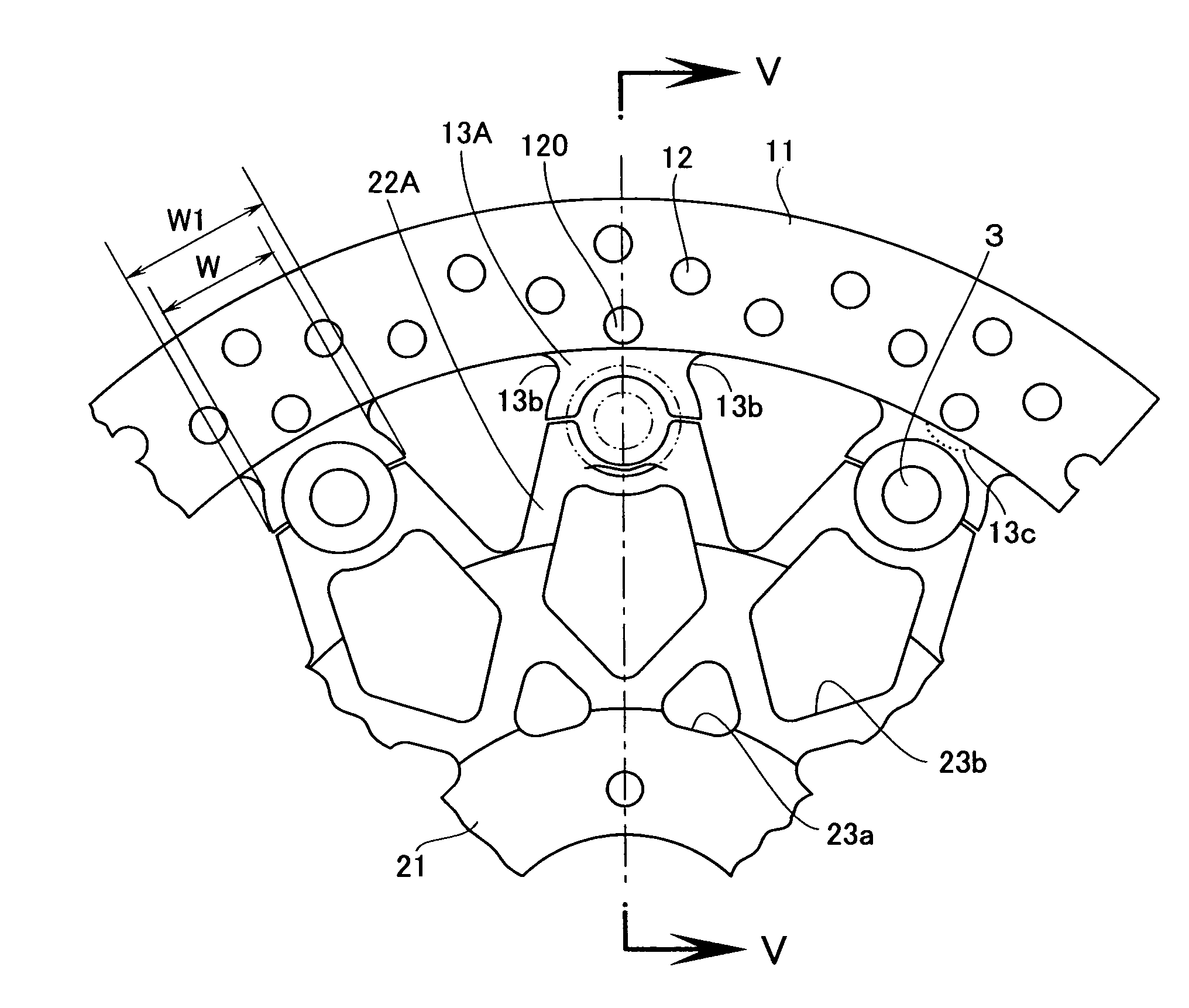
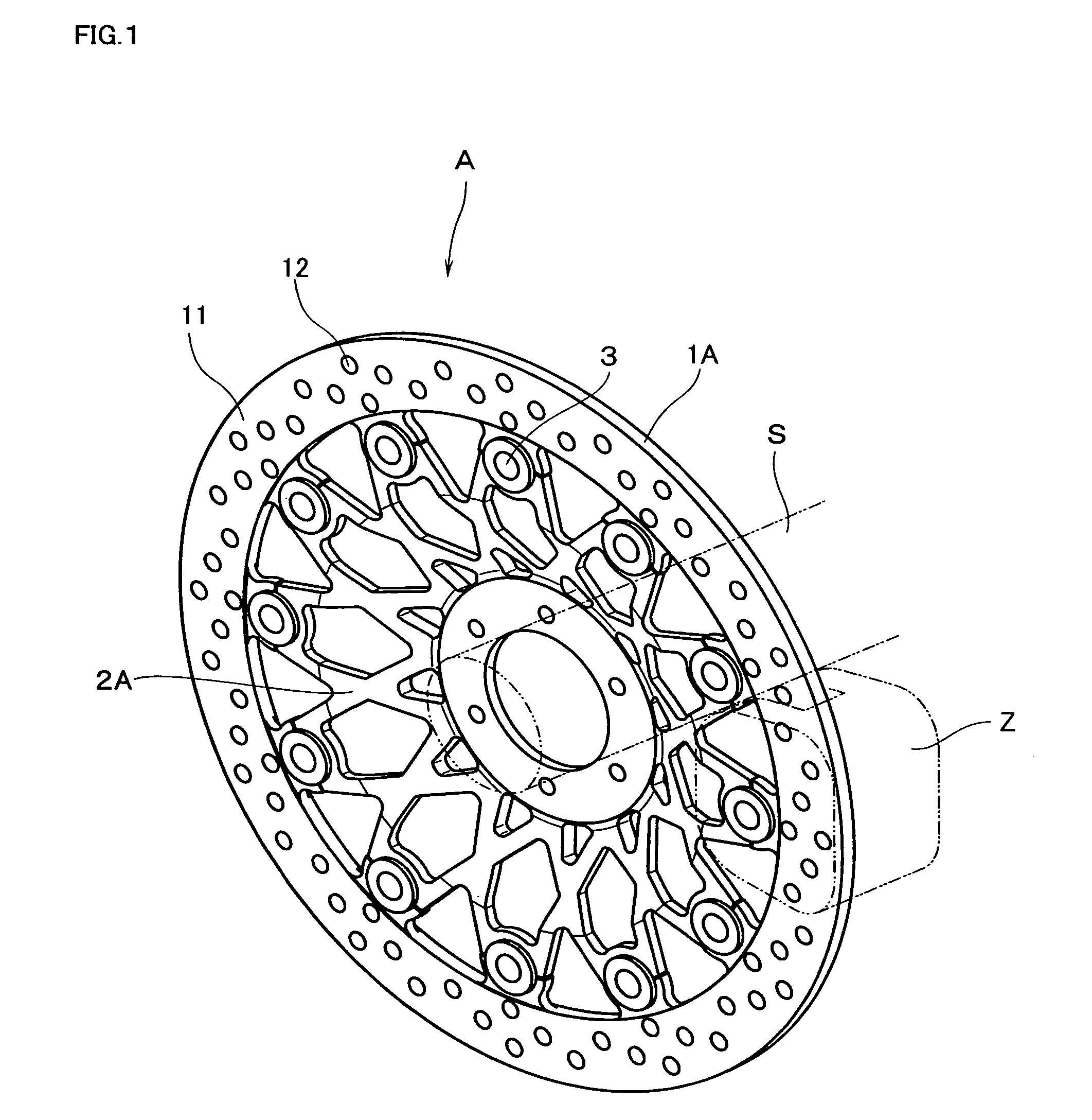
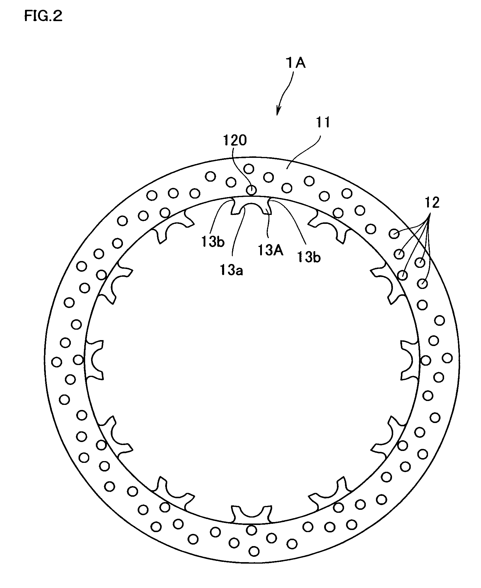
[0097]In the example 1, the disc brake A of the first embodiment shown in FIG. 1 was manufactured and temperature distribution of the rotor portion 11 during braking operations was measured. The braking rotor 1A was made of stainless steel and cutouts portions 13b of circular arc configuration were formed at either side of each projection 13A (In this case, the cross sectional area at a portion of minimum width in which the cutout portion 13b is formed is set at 85% of that in which no cutout is formed). In addition one through aperture 120 was formed at the boundary between the rotor portion 11 and each projection 13A.
[0098]The test was carried out using a commercially available caliper and brake pads under conditions; inertial mass: 1.25 Kgf·m·S2, speed of rotation: 1760 rpm, deceleration: 0.7 G, brake oil pressure: 14 Kgf / cm2. The number of braking was one time. A picture showing the temperature distribution of the rotor portion 11 immediately after stop of the disc brake A is sh...
example 2
[0102]In the Example 2, the temperature distribution in the rotor portion 11 during braking operations was measured as to the disc brake B of the second embodiment shown in FIG. 6. The braking rotor 1B was made of stainless steel and cutouts portions 131 of circular arc configuration were formed at either side of each projection 13B and cutouts 121 were formed in the inner circumferential portion of the rotor portion 11.
[0103]The test was carried out using a commercially available caliper and brake pads under conditions; inertial mass: 1.25 Kgf·m·S2, speed of rotation: 1650 rpm, deceleration: 0.6 G, and the number of braking: one time. A picture showing the temperature distribution of the rotor portion 11 immediately after stop of the disc brake B is shown in FIG. 21(a) and the temperature distribution on a radial line (shown by a dotted line in FIG. 21(a)) passing through a portion near the cutouts 121 is shown in FIG. 21(b).
example 3
[0104]In the Example 3, similarly to the Example 2, the temperature distribution in the rotor portion 11 during braking operations was measured as to the disc brake B. The braking rotor 1B was made of stainless steel however different from the Embodiment 2, no cutouts portions 131 of circular arc configuration were formed at either side of each projection 13B and no cutouts 121 were formed either in the inner circumferential portion or the outer circumferential portion of the rotor portion 11. On the contrary, the cross sectional area of each through aperture 123 formed in a projected region of the projection 13B was determined as having a same cross sectional area as each through aperture 12 formed in the rotor portion 11.
[0105]The test was carried out using a commercially available caliper and brake pads under conditions; inertial mass: 1.25 Kgf·m·S2, speed of rotation: 1650 rpm, deceleration: 0.6 G, and the number of braking: one time. A picture showing the temperature distributi...
PUM
 Abstract
Description
Claims
Application Information
 - R&D
- Intellectual Property
- Life Sciences
- Materials
- Tech Scout
- Unparalleled Data Quality
- Higher Quality Content
- 60% Fewer Hallucinations
Browse by: Latest US Patents, China's latest patents, Technical Efficacy Thesaurus, Application Domain, Technology Topic, Popular Technical Reports.
© 2025 PatSnap. All rights reserved.Legal|Privacy policy|Modern Slavery Act Transparency Statement|Sitemap|About US| Contact US: help@patsnap.com