Ball and socket joint with sensor device and process for wear measurement

a sensor device and ball socket technology, applied in the direction of suspensions, instruments, couplings, etc., can solve the problems of complex and hence expensive manufacture high cost of wire wiring of such ball socket joints, and inability to meet the requirements of wear measurement, etc., to achieve reliable and reliable manner, overcome the drawbacks of the state of the art

Inactive Publication Date: 2010-07-27
ZF FRIEDRICHSHAFEN AG
View PDF19 Cites 18 Cited by
  • Summary
  • Abstract
  • Description
  • Claims
  • Application Information

AI Technical Summary

Benefits of technology

[0008]Against this background, the object of the present invention is to provide a ball and socket joint with a sensor device, with which the drawbacks of the state of the art can be overcome. In particular, the ball and socket joint shall make it possible to determine forces and loads acting on the ball and socket joint at a low cost and in a reliable manner as well as with a high degree of freedom in terms of design. In addition, it shall also be possible to obtain information on the state of wear of the ball and socket joint, so that a possibly imminent failure of a ball and socket joint can be recognized and thus prevented in time.

Problems solved by technology

However, the equipping of ball and socket joints with such wire strain gauges or piezo sensors is associated with a rather substantial effort.
On the whole, this leads to a complicated and hence expensive manufacture of such ball and socket joints provided with load sensors, and, moreover, the exposed sensor system and wiring of such ball and socket joints are sensitive and therefore threatened by failures.
In addition, it is hardly possible in the prior-art ball and socket joints with force sensor device to derive additional information on the state especially of the ball and socket joint by means of the force sensor device beyond the load situation proper of the ball and socket joint.
However, since ball and socket joints arranged in the area of the chassis or the steering of motor vehicles are safety-relevant components, whose failure may lead to fatal consequences especially during driving, it is especially desirable to make it also possible to permanently obtain information on the instantaneous operating state or state of wear of the ball and socket joint.

Method used


Image

  • Ball and socket joint with sensor device and process for wear measurement
  • Ball and socket joint with sensor device and process for wear measurement
  • Ball and socket joint with sensor device and process for wear measurement

Examples


Embodiment Construction

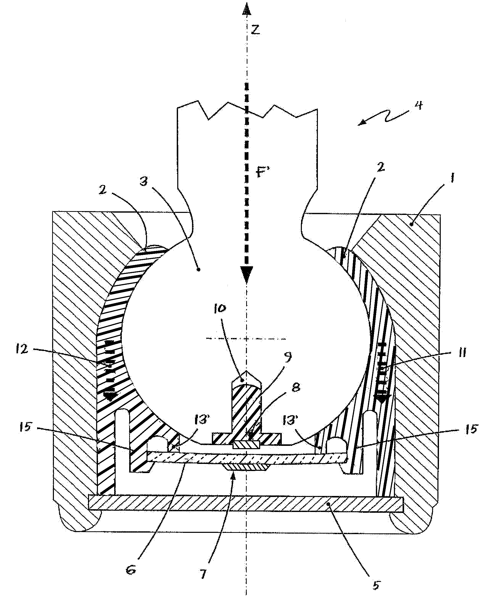
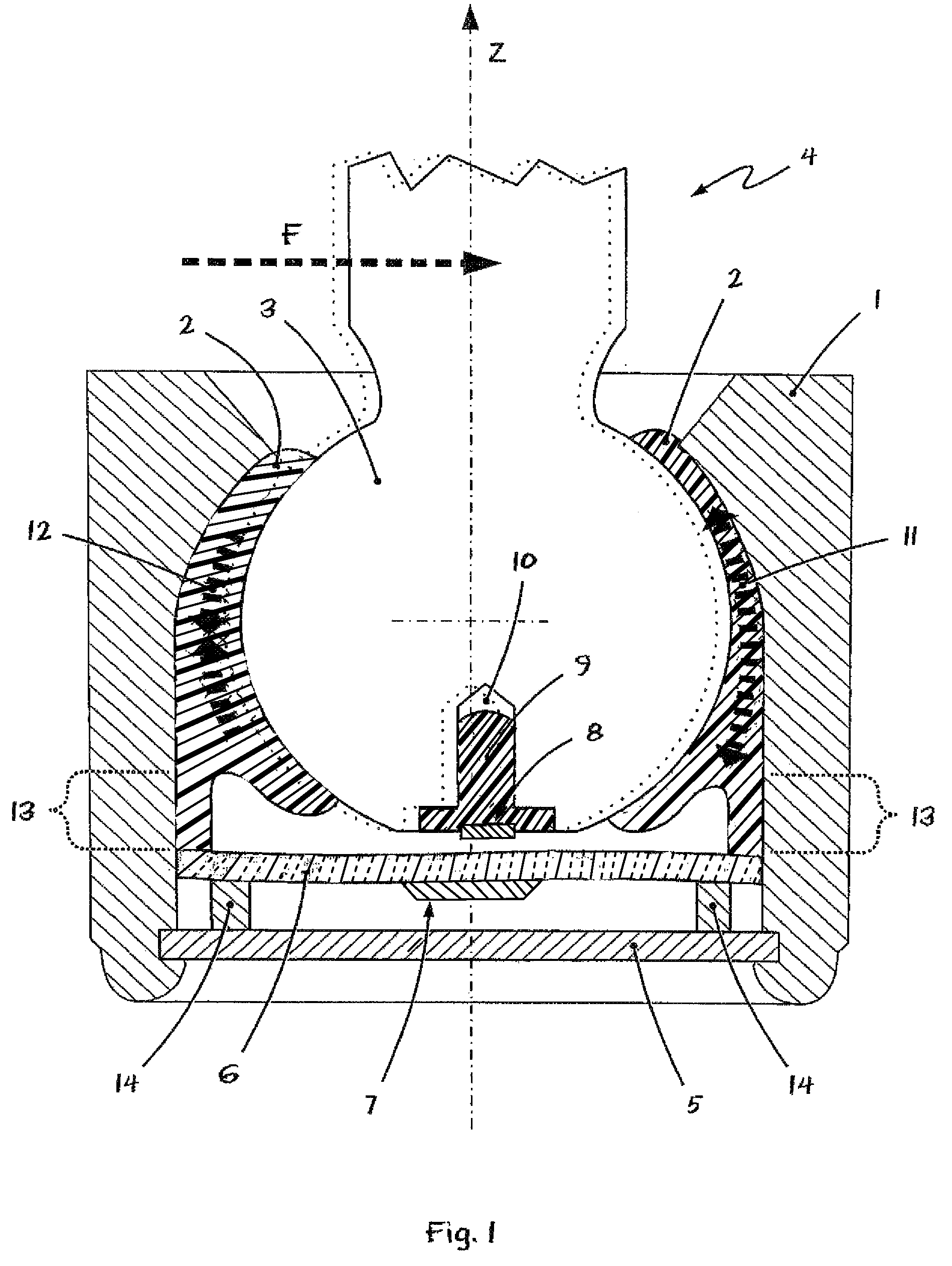
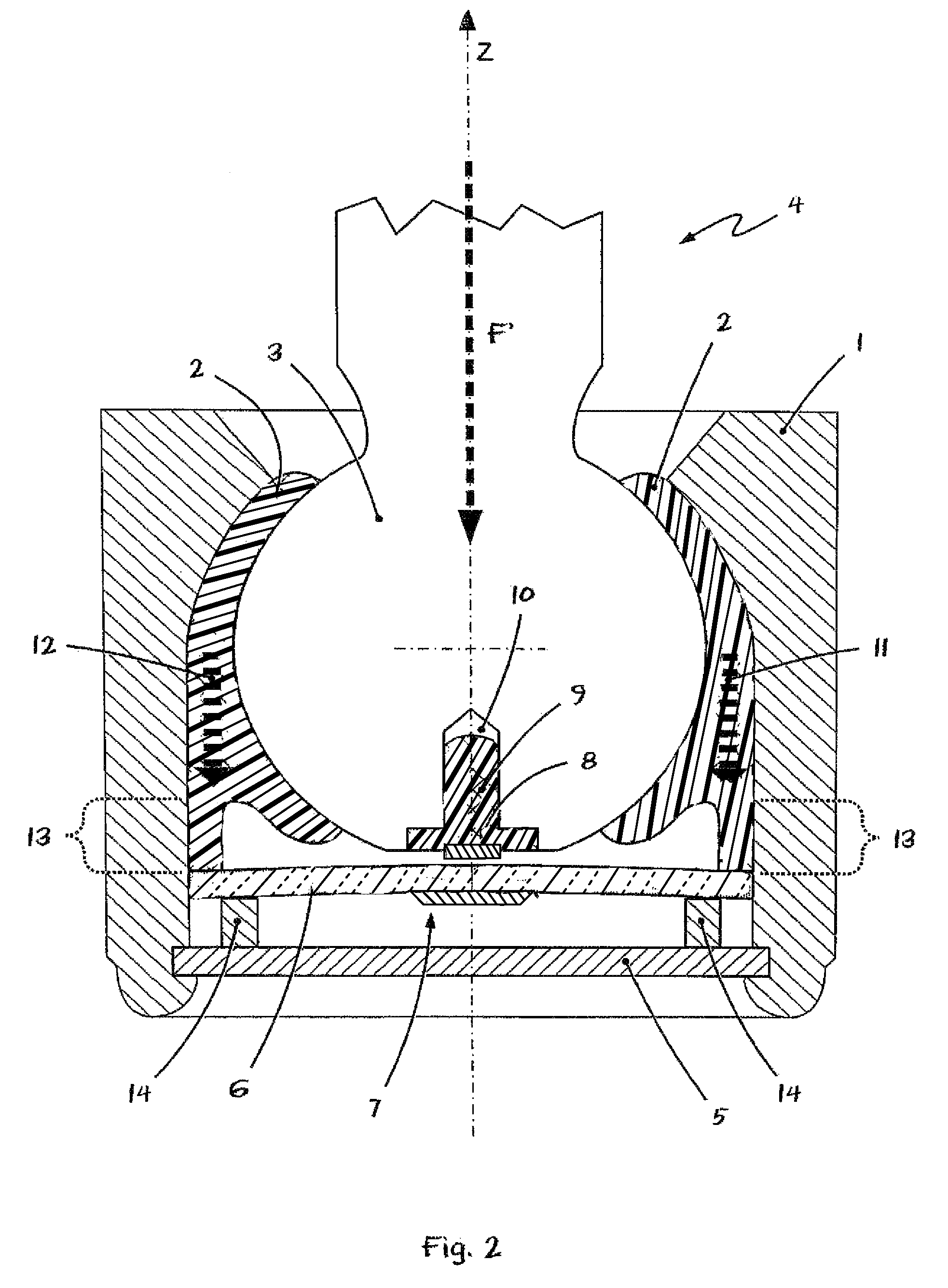
[0043]Referring to the drawings in particular, FIG. 1 shows, in a schematic longitudinal view, an embodiment of a ball and socket joint according to the present invention. The essentially pot-shaped joint housing 1 with the bearing shell or ball shell 2 arranged therein is recognized. The ball 3 of a ball pivot 4 is, in turn, arranged in the interior space of the ball shell 2.

[0044]The ball and socket joint according to FIG. 1 has, furthermore, a sensor printed circuit board 6 arranged between the joint ball 3 and the housing cover 5. A sensor device 7, indicated only schematically, is arranged on the sensor printed circuit board 6. The sensor device 7 is located in the vicinity of a magnetic field transducer 8, which is designed as a permanent magnet and is arranged in a hole 10 of the joint ball 3 by means of a plastic plug 9.

[0045]The sensor device 7 is designed such that it can detect the field of the permanent magnet 8 in all three directions of space; in other words, it can co...


PUM


Abstract

A ball and socket joint is provided for a motor vehicle that has a joint housing (1), in the interior space of which a ball shell (2) is arranged. The ball (3) of a ball pivot (4) is accommodated in the ball shell (2). A sensor device (7), for measuring forces and loads, is arranged on a flexurally elastic printed circuit board (6). The printed circuit board is fastened in the joint housing (1) in a flexurally mobile manner. The sensor device (7) measures deflections and mechanical stresses of the sensor printed circuit board (6). A transmission device introduces forces or a bending moments into the sensor printed circuit board (6) in case of a deformation of the ball shell (2). The process makes possible the permanent determination of the state of wear of the ball and socket joint via measurement of the prestressing force of the ball shell.

Description

CROSS REFERENCE TO RELATED APPLICATIONS[0001]This application is a United States National Phase application of International Application PCT / DE2006 / 001019 and claims the benefit of priority under 35 U.S.C. §119 of German Patent Application DE 10 2005 027 826.4 filed Jun. 15, 2005, the entire contents of which are incorporated herein by reference.FIELD OF THE INVENTION[0002]The present invention pertains to a ball and socket joint with a sensor device, for example, for an axle system or a wheel suspension of a motor. Furthermore, the present invention pertains to a process for wear measurements on a ball and socket joint.BACKGROUND OF THE INVENTION[0003]Ball and socket joints of the type mentioned in the introduction are used, for example, but by no means exclusively, at the chassis or at the wheel suspension of motor vehicles, e.g., as a support joint or as a guiding joint. Ball and socket joints of this class comprise a sensor device, with which forces and loads acting on the ball ...

Claims


Application Information

Patent Timeline
Patent Type & Authority Patents(United States)
IPC IPC(8): F16C11/08
CPCB60D1/30B60D1/305B60D1/58F16C11/0647Y10T403/32631Y10T403/32713Y10T403/32196Y10T403/32721F16C11/0604F16C11/0633F16C11/0642F16C17/246F16C41/00F16C2233/00F16C2326/05F16C11/00F16C11/06
Inventor ERSOY, METINSPRATTE, JOACHIMKLANK, MICHAELHOFMANN, PETER
Owner ZF FRIEDRICHSHAFEN AG
Why Eureka
Try Eureka