Actuating device with an additional switching element

a technology of switching element and actuating device, which is applied in the direction of control device, gearing control, gearing element, etc., can solve the problems of comparatively complicated and expensive mounting of prior-art actuating device, connection cable fatigue, damage or failure of signal transmission, etc., and achieve the effect of overcoming the drawbacks of the state of the ar

Inactive Publication Date: 2014-06-17
ZF FRIEDRICHSHAFEN AG
View PDF28 Cites 5 Cited by
  • Summary
  • Abstract
  • Description
  • Claims
  • Application Information

AI Technical Summary

Benefits of technology

[0011]Against this background, the object of the present invention is to provide an actuating device for a technical system, for example, for actuating a speed-change gear, which has an additional switching element and with which the drawbacks of the state of the art can be overcome. In particular, the actuating device shall avoid the problem of a delicate cabling and of the insufficient protection of the electric contact maker, which problem is associated with the arrangement of the additional switching element which is present in the state of the art.
[0014]The fastening of the signal transmitter in the base area of the actuating device entails, in other words, that the signal transmitter is both arranged in the base area such that it is protected optimally and, furthermore, the cabling between the signal receiver and the signal transmitter can also be mounted rigidly and immovably as a continuous cabling.
[0017]According to a preferred embodiment of the present invention, the signal transmitter is, however, a Hall sensor. The design of the actuating device according to the present invention with a Hall sensor is advantageous because contactless transmission of the switching signal from the actuating element to the base area of the actuating device or to the signal transmitter is made possible in this manner. The contactless transmission of the switching signal is free from maintenance and wear, and is thus favorable for the long-term and reliable function of the actuating device.
[0018]According to other embodiments of the present invention, the signal transmitter is designed as an optical sensor or as a microswitch. An optical sensor has, since it likewise operates in a contactless manner, advantages similar to those of a Hall sensor, while a signal transmitter designed as a microswitch can be embodied, for example, at an especially low cost. Since microswitches also handle a large number of switching cycles, a reliable actuating device with long service life can be embodied in case of the use of a microswitch as well.
[0023]According to an alternative embodiment of the present invention, the additional switching element is used to start and / or stop the engine of a motor vehicle. The operating comfort of the motor vehicle is improved in this manner, because there is a close chronological relationship between starting the engine and engaging a gear and they can thus also be advantageously standardized from the viewpoint of operation.

Problems solved by technology

However, the electrical line is also moved along in this case during motion of the actuating lever in the area in which the actuating lever is connected to the lever base and is even deformed by bending each time.
This continual bending deformation of the electrical line connection between the additional switching element and the lever base may, however, lead to fatigue of the connection cable and ultimately to damage to or failure of the signal transmission between the additional switching element and the switching receiver.
However, both require great care during assembly and thus lead to a comparatively complicated and expensive mounting of the prior-art Actuating device with additional switching element.
Such additional external effects, for example, shocks during motion and at the end stop of the operating element, abusive forces, or even intense heating, especially in the motor vehicle, may lead to premature aging or failure of the electrical switching element.
However, this is hardly acceptable, especially when such an additional switching element is used for applications that are critical in terms of safety.

Method used


Image

  • Actuating device with an additional switching element
  • Actuating device with an additional switching element
  • Actuating device with an additional switching element

Examples


Embodiment Construction

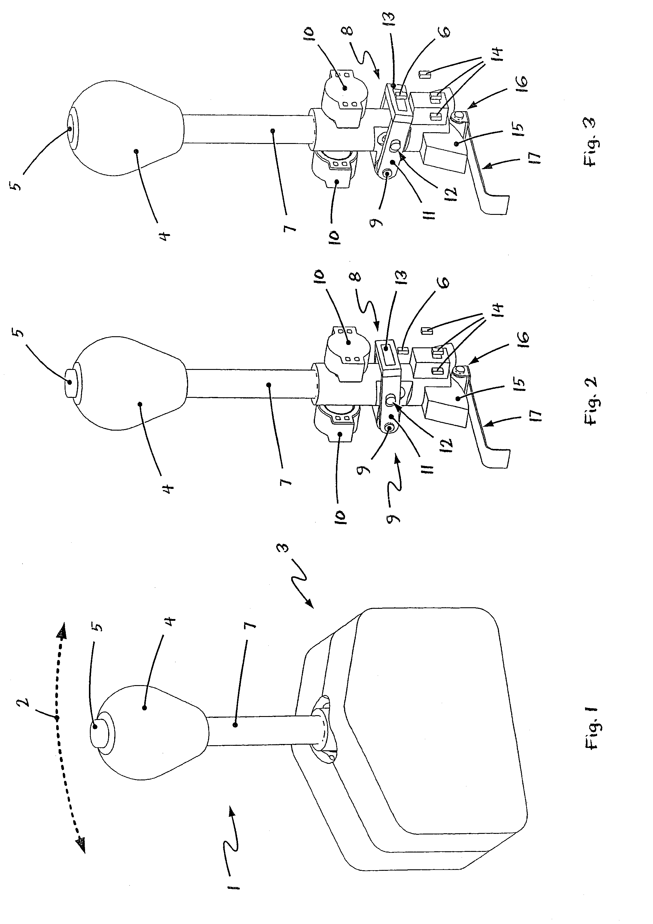
[0035]Referring to the drawings in particular, FIG. 1 shows a schematic isometric representation of an embodiment of an actuating device according to the present invention. This exemplary embodiment is an actuating device for an automatic vehicle transmission.

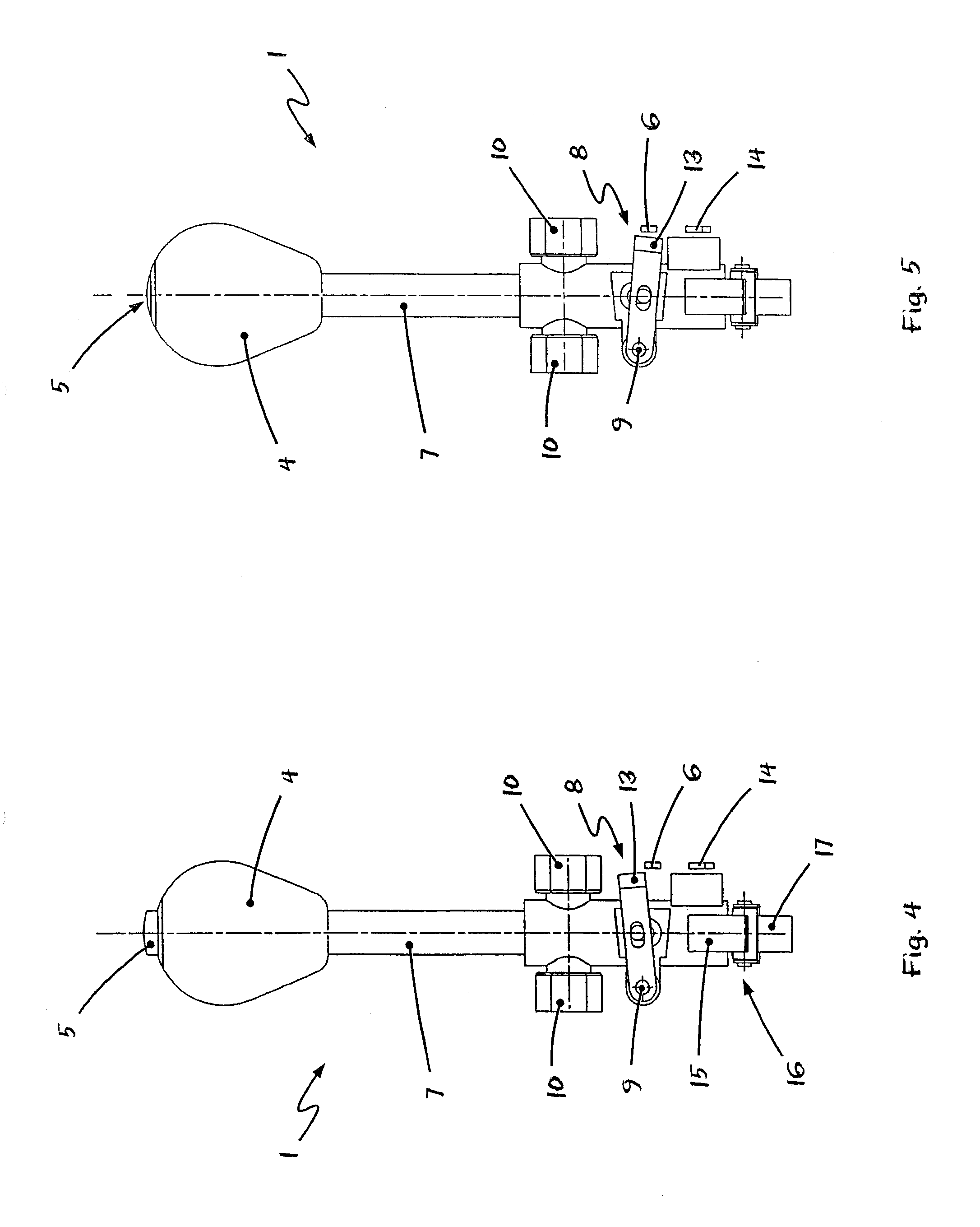
[0036]The representation in FIG. 1 shows the actuating element 1, which is designed as a gearshift lever and is arranged such that it can perform a pivoting motion along the broken line 2 relative to a base area 3. The gearshift lever 1 can thus move forward and backward in the direction of travel in order to thus select, for example, the different gears of an automatic transmission.

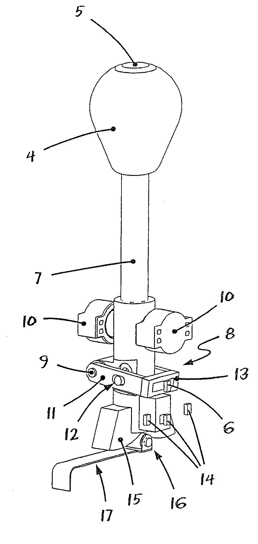
[0037]FIG. 1 shows, furthermore, the additional switching element 5, which is arranged in the area of the knob 4 of the gearshift lever 1 and is designed as a push switch or pushbutton 5 in the exemplary embodiment being shown. Additional functions of the motor vehicle can be controlled with this pushbutton 5; for example, the parking brake of the a...


PUM


Abstract

An actuating device for a technical system, especially for selecting gears of a shift-by-wire speed-change gear. The actuating device includes an actuating element (1), which is movable in relation to a base area (3), with at least two switching positions. At least one additional switching element (5), which acts on a signal transmission (8) with a signal transmitter (6), is arranged at the actuating element (1). The additional switching element (5) and the signal transmitter (8) are connected by a mechanical transmission element. However, the signal transmitter (6) is connected to the base area (3) of the actuating device. The present invention makes it possible to embody a robust additional switching element, which is protected from disturbances, at an actuating element. Mobile and hence susceptible cablings to the additional switching element, which were hitherto necessary, are eliminated.

Description

CROSS REFERENCE TO RELATED APPLICATIONS[0001]This application is a United States National Phase application of International Application PCT / DE2006 / 001645 and claims the benefit of priority under 35 U.S.C. §119 of German Patent Application DE 10 2005 044 254.4 filed Sep. 15, 2005, the entire contents of which are incorporated herein by reference.FIELD OF THE INVENTION[0002]The present invention pertains to a device for manually controlling or actuating a technical system for example, for selecting gears of a shift-by-wire speed-change gear, the actuating device including an actuating element, which is mobile (movable) relative to a base area, with at least two switching positions, wherein at least one additional switching element is arranged at said actuating element, which additional switching element acts on a signal transmission device with a signal transmitter.BACKGROUND OF THE INVENTION[0003]Actuating devices of this type are used, for example, but by no means exclusively, for ...

Claims


Application Information

Patent Timeline
Patent Type & Authority Patents(United States)
IPC IPC(8): F16H59/12F16H59/10
CPCF16H59/10F16H59/105F16H59/0217Y10T74/2003Y10T74/2014
Inventor GIEFER, ANDREASMEYER, JORG
Owner ZF FRIEDRICHSHAFEN AG
Why Eureka
Try Eureka