Push button with cable

a technology of push-button and cable, which is applied in the direction of mechanical control devices, manual control with single controlling member, instruments, etc., can solve the problems of high cost in order to ensure the function of push-button actuation, thermal expansion, and other problems, to achieve the effect of saving mounting costs, overcoming drawbacks of the state of the art, and facilitating mounting

Inactive Publication Date: 2014-08-19
ZF FRIEDRICHSHAFEN AG
View PDF27 Cites 4 Cited by
  • Summary
  • Abstract
  • Description
  • Claims
  • Application Information

AI Technical Summary

Benefits of technology

[0011]Against this background, the object of the present invention is to provide a push-button device with which the drawbacks of the state of the art can be overcome. In particular, the push-button device shall permit the mechanically separate arrangement of the push button and the technical system to be controlled. Impairment of the actuation of the technical system by means of the push button or impairment of the precision of the push-button device due to tolerances between the installation sites of the push button and the technical system shall be permanently avoided in a simple manner, as a result of which mounting shall be facilitated, mounting costs shall be saved and permanent operational reliability and the maintenance-free nature of the push-button device shall be guaranteed.
[0013]An actuating device with improved reliability and failsafeness is created by the present invention. The need for the complicated adjustment of the mechanical connection between the push button and the system to be controlled as a consequence of unavoidable dimensional tolerances between the corresponding installation sites is now eliminated in a simple and cost-effective manner. The effects of changes in distances and positions on switching precision and the reliability of mechanical push-button device, for example, as a consequence of thermal expansions, are also eliminated with the present invention.
[0018]According to a preferred embodiment of the present invention, the cable means comprises, in the manner of a Bowden cable, a cable for transmitting pulling forces. This embodiment has the advantage of having a simple and inexpensive design as well as high reliability. The cable means as well as the mechanisms of the push-button device as well as the technical system are reset after the actuation, for instance, by means of one or more resetting springs, at least one resetting spring being arranged in the area of the technical system in order to return, starting from there, the cable as well as optionally also the actuating mechanisms in the technical system as well as in the push-button device into the starting position after actuation of the push button.
[0019]According to an alternative embodiment of the present invention, the cable means comprises a flexible wire for transmitting pulling and / or compressive forces between the push-button device and the technical system being controlled. A cable means with a flexible wire, which also permits, in particular, compressive forces to be transmitted, has various advantages. For example, the shape of the push-button device can thus be simplified in such a way that the compressive force applied during the actuation of the push button is directly transmitted to the flexible wire. The otherwise necessary conversion of the compressive force generated at the push button into a pulling force compatible with a cable can thus be eliminated. As an alternative or in addition hereto, this embodiment also has the advantage that the entire actuating mechanism including the push button and the cable means as well as optionally including the actuating elements being moved in the system being controlled can be moved back into the inoperative position from the actuation position with only a single resetting spring, and the compression spring may optionally be arranged in the area of the push-button device or in the area of the system to be controlled.
[0020]According to another embodiment of the present invention, a reversing lever is arranged in a pivotingly movable manner at the holding means of the push-button device. The reversing lever is used to convert the compressive forces introduced via the push button into pulling forces, which can be used especially to actuate a cable. The cable, which is especially inexpensive but can be used to transmit pulling forces only, can thus be used to transmit the compressive forces applied to the push button to the system to be controlled.
[0023]A number of other advantages can thus be achieved. Thus, thanks to the additional electrical contact, the actuation of the system to be controlled can take place during normal operation, for example, by means of the electrical contact, whereas the mechanical connection between the push button and the system to be controlled by means of the cable means represents a redundancy fall-back level, which guarantees reliable actuation of the system to be controlled even in case of failure of the electrical function.

Problems solved by technology

However, the statements made above are not true especially when there is no electrical connection between the push button and the technical system to be connected, but the technical system is rather in mechanical connection with the push button.
However, the technical systems controlled herewith are usually not anchored on the surface of, for example, the instrument panel or the center console, but are rather connected to a carrier that is located under it and is a rigid part of the body or to the body itself.
These distance tolerances between the installation site of the push button and the installation site of the technical system to be controlled must then be compensated by means of a separate setting operation in a complicated manner and hence at a high cost in order to ensure the function of the push-button actuation.
Furthermore, thermal expansions may also occur, which assume quite substantial orders of magnitude in case of the temperature differences occurring in a motor vehicle.
The precision of the mechanical connection between the push button and the technical system to be controlled suffers in such a case.
Automatic triggering of the function of the technical system or failure of the ability of the technical system to be operated, for example, because of thermal expansions, may occur in the worst case.

Method used


Image

  • Push button with cable
  • Push button with cable
  • Push button with cable

Examples


Embodiment Construction

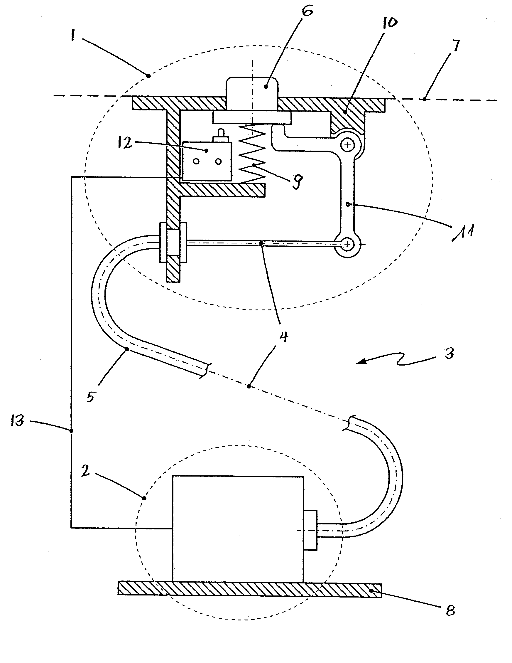
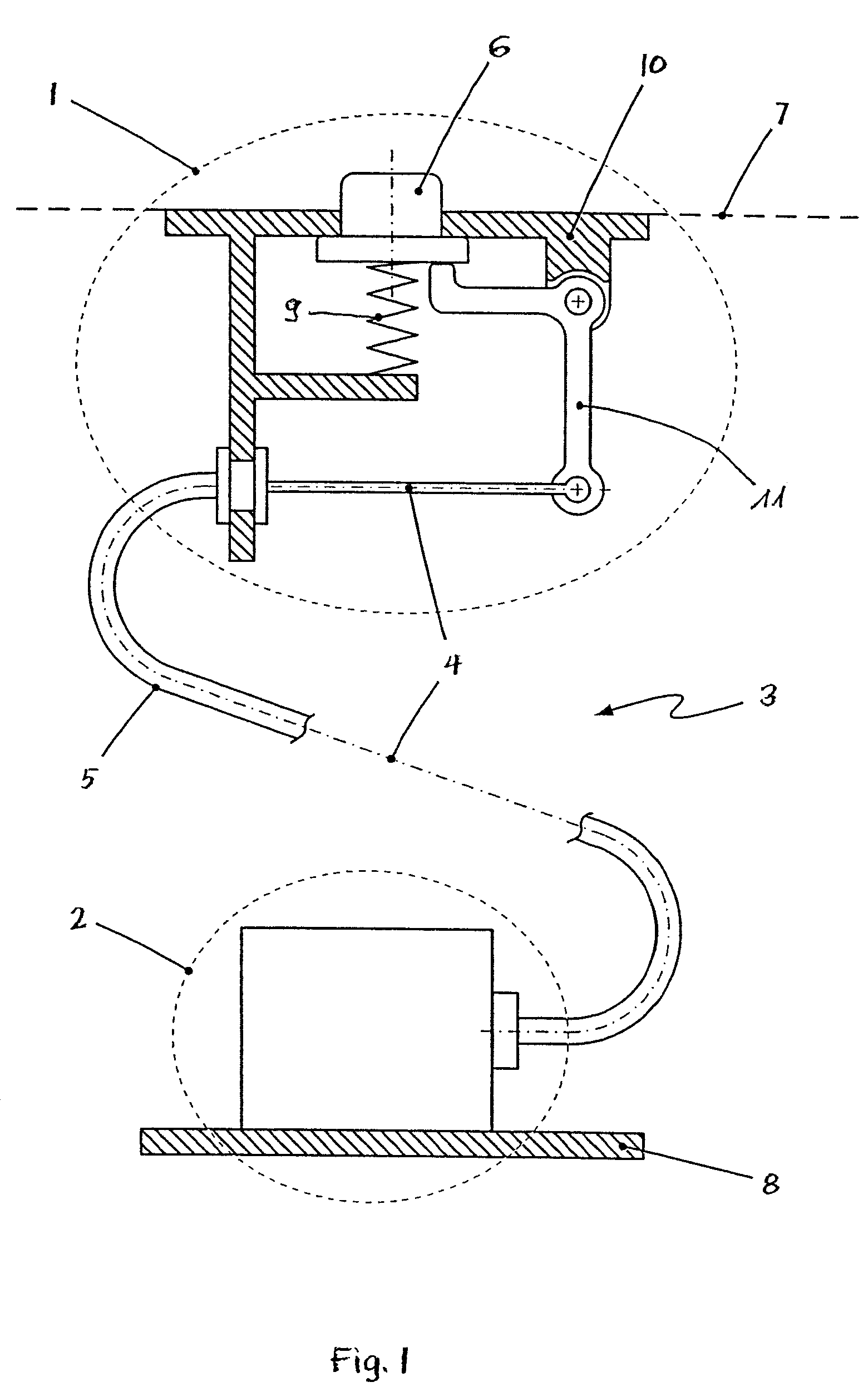
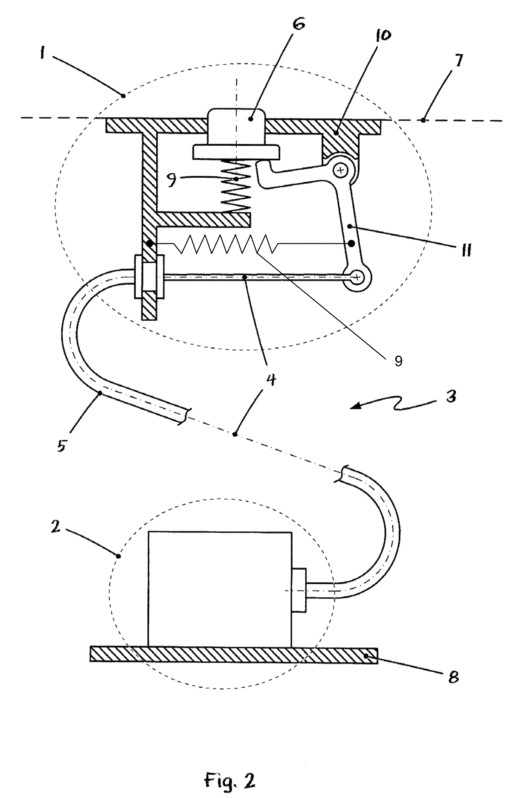
[0030]Referring to the drawings in particular, FIG. 1 schematically shows a first embodiment of a push-button device according to the present invention. The push button 1, the system 2 to be controlled, which is indicated only schematically, as well as the cable means 3 are recognized at first. The cable means 3 comprises a flexible pulling cable and a likewise flexible outer sheath 5, which together form a cable 4, and it is used to pass on the switching commands initiated via the push button 6 to the system 2 to be controlled.

[0031]Since both the outer sheath 5 and the pulling cable are supported at their respective ends at the push-button device 1 and at the system 2 to be controlled, changes in the relative positions between the push-button device 1 and the system 2 to be controlled do not lead to any changes in the relative positions of the outer sheath 5 and the pulling cable. However, such changes in positions between the push-button device 1 and the system 2 to be controlled...


PUM


Abstract

A push-button device (1) is provided for actuating a technical system (2), especially in a motor vehicle. The push-button device (1) comprises at least one push button (6) as well as a holding device (10). The push button (6) is arranged in the holding device (10) and can be moved between a neutral position and an actuation position. The push-button device (1) is characterized according to the present invention in that a flexible cable device (3) for signal transmission is arranged between the push button (6) and the technical system (2).

Description

CROSS REFERENCE TO RELATED APPLICATIONS[0001]This application is a United States National Phase application of International Application PCT / DE2005 / 001798 and claims the benefit of priority under 35 U.S.C. §119 of German Patent Application DE 10 2004 049 435.5 filed Oct. 8, 2004, the entire contents of which are incorporated herein by reference.FIELD OF THE INVENTION[0002]The present invention pertains to a push-button device for actuating a technical system, especially in a motor vehicle, and more particularly to a push-button device with at least one push button as well as a holding means in which the push button, movable between a neutral position and an actuation position, is arranged.BACKGROUND OF THE INVENTION[0003]Push buttons and push-button devices of the type mentioned in the introduction are used, for instance, but by no means exclusively, in motor vehicles in the passenger compartment or within easy reach of the driver. Such push buttons are used in such applications to ...

Claims


Application Information

Patent Timeline
Patent Type & Authority Patents(United States)
IPC IPC(8): H01H17/00F16C1/10F16C1/12G05G1/02G05G7/02G05G7/04H01H3/36
CPCG05G1/02G05G7/02H01H3/36F16C1/10F16C1/12G05G7/04E05B79/20E05B81/90F16C2350/52
Inventor MEYER, JORGGIEFER, ANDREASKLIEMANNEL, WOLFGANGRAKE, LUDGER
Owner ZF FRIEDRICHSHAFEN AG
Why Eureka
Try Eureka