Double-row angle pin connector

a technology of angle pins and connectors, applied in the direction of coupling contact members, fixed connections, coupling device connections, etc., can solve the problems of insufficient protection of angle pins of such connectors, inability to reliably guarantee the intended flow of current, and excessive plugging forces, etc., to overcome the drawbacks of the state of the art and achieve reliable operation.

Inactive Publication Date: 2010-02-02
ZF FRIEDRICHSHAFEN AG
View PDF9 Cites 0 Cited by
  • Summary
  • Abstract
  • Description
  • Claims
  • Application Information

AI Technical Summary

Benefits of technology

[0010]Against this background, the object of the present invention is to provide an angle pin connector with which the drawbacks of the state of the art can be overcome. In particular, the angle pin connector shall be able to be designed such that it is especially reliable in operation also and precisely in case of the use of the, especially inexpensive and compact embodiments of angle pin connectors, which make do without extrusion coating of their own and without a plug housing of their own, and the axial displacements of connection pins caused by plug forces shall thus be reliably prevented from occurring.
[0013]In other words, this means that, unlike in the state of the art, at most the soldered ends of the angle pins arranged in the outer row can be clamped and thus fixed between the housing bottom and the housing cover during the mounting of the housing. Thanks to the housing support straps according to the present invention, which surround the soldered ends arranged in the outer row in an arched manner and thus supportingly meet the soldered ends arranged in the inner, patch plug-side row, the soldered ends arranged in the inner row can rather also be clamped now between the housing bottom and the housing cover in a positive-locking manner and thus protected against displacement or bending.
[0014]This is especially advantageous because the present invention thus provides especially reliably operating and robust angle pin connectors, which, however, make do without an extrusion coating of their own or without a plug housing of their own in case of installation. The costs of embodying multi-pole plug-in connections that are of a high quality and meet high safety requirements to assembly units can thus be reduced by up to one order of magnitude.
[0016]According to a preferred embodiment of the present invention, the support straps are arranged, however, in the housing cover, while the plugged ends of the angle pins are arranged or fixed in the housing bottom. This makes it possible to arrange or preassemble all assembly units, including the printed circuit board carrying the angle pin connector, in the housing bottom. The housing cover is then finally mounted, and the support straps arranged in the housing cover surround the angle pins of the outer pin row and thus push and consequently fix the angle pins of the inner pin row into a corresponding contact with the housing bottom.
[0021]The present invention is embodied independently from the size and the structural shape of the housing parts, as long as the arrangement of the support straps according to the present invention is implemented. However, according to an especially preferred embodiment of the present invention, at least one of the two housing parts, and preferably both housing parts, are formed by a component or a housing component each of a higher-level assembly unit. This is especially advantageous because multi-pole patch plugs can be embodied in this manner on assembly units in an especially simple and extremely inexpensive manner, for example, by the plug and jack contour as well as the mount of the angle pins are also integrated or extrusion-coated into the corresponding housing component.
[0023]To facilitate the preassembly of the angle pin connector, the angle pins may, furthermore, be arranged and fixed, as this is also provided for according to another, preferred embodiment of the present invention, in a common mounting or spacer strip. This facilitates the handling of the pins belonging to an angle pin connector as one unit and at the same time ensures compliance with the specified spaces between the pins before the final mounting.

Problems solved by technology

However, the latter angle pin connectors, though being especially inexpensive and, moreover, compact, have the drawback that the angle pins of such connectors are protected insufficiently against displacement of the patch plug-side ends in the axial direction of these ends.
Such excessively strong plugging forces may occur, for example, when contact pins or contact prongs are deformed, contaminated or corroded or when the plug is not moving exactly in parallel to the contact pins during insertion but is inserted in a tilted position.
However, such a deformation of connection pins is problematic because they may cause especially contact problems, and the intended flow of current is thus no longer reliably guaranteed in the deformed connection pins affected.
The deformation of individual angle pins may even cause short-circuits in the area of the angle pin connector, especially when plug-side, inner angle pins are deformed to such an extent that they come into contact with the outer connection pins located at the same level in the other row.
Therefore, only the angle pins of the outer pin row have hitherto been often supported, but the problem mentioned at the beginning, namely, the risk of bending during pushing in and possibly also during the pulling out of the plug, has continued to be present in the angle pins of the inner pin row.

Method used


Image

  • Double-row angle pin connector
  • Double-row angle pin connector
  • Double-row angle pin connector

Examples


Embodiment Construction

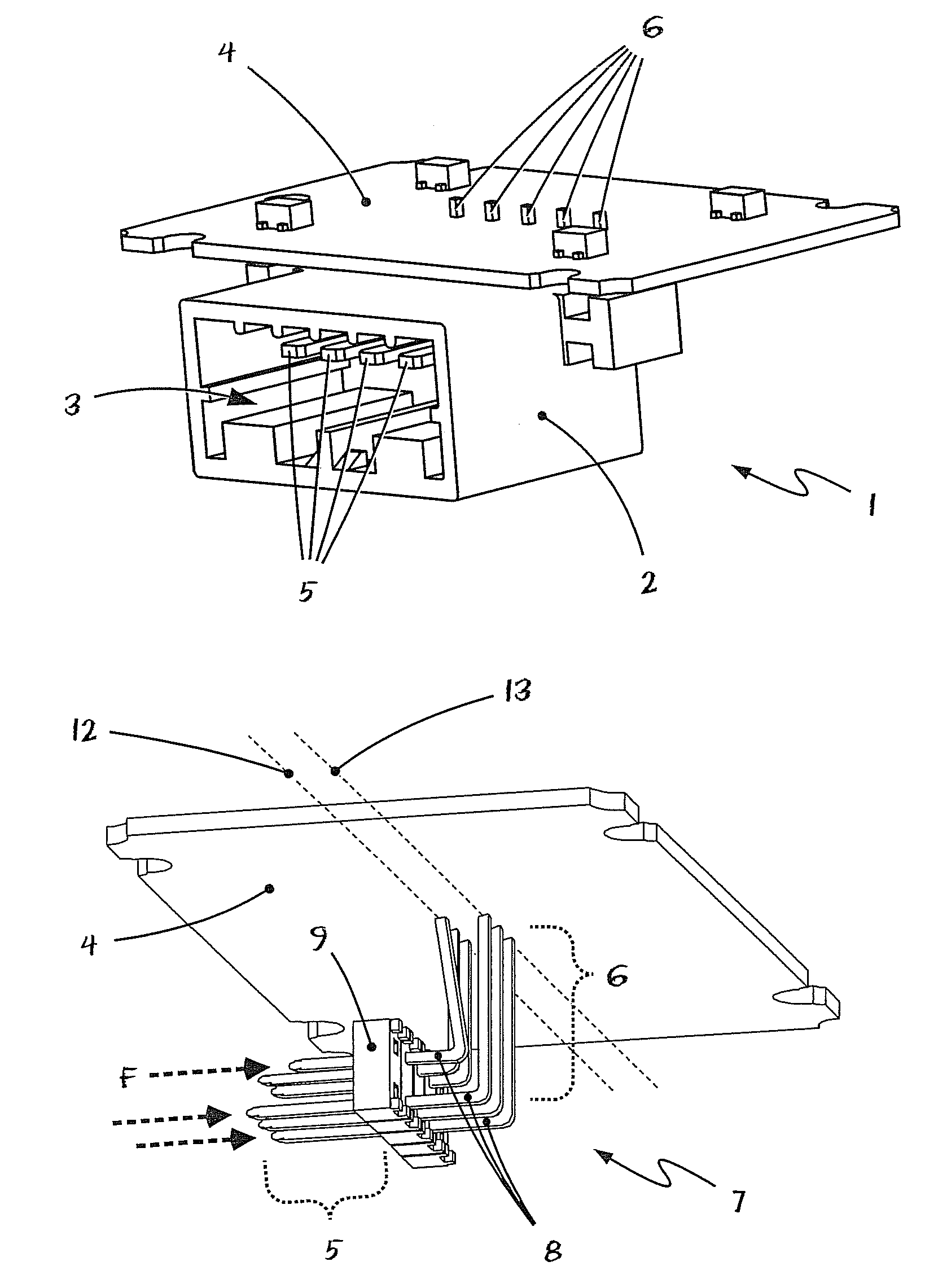
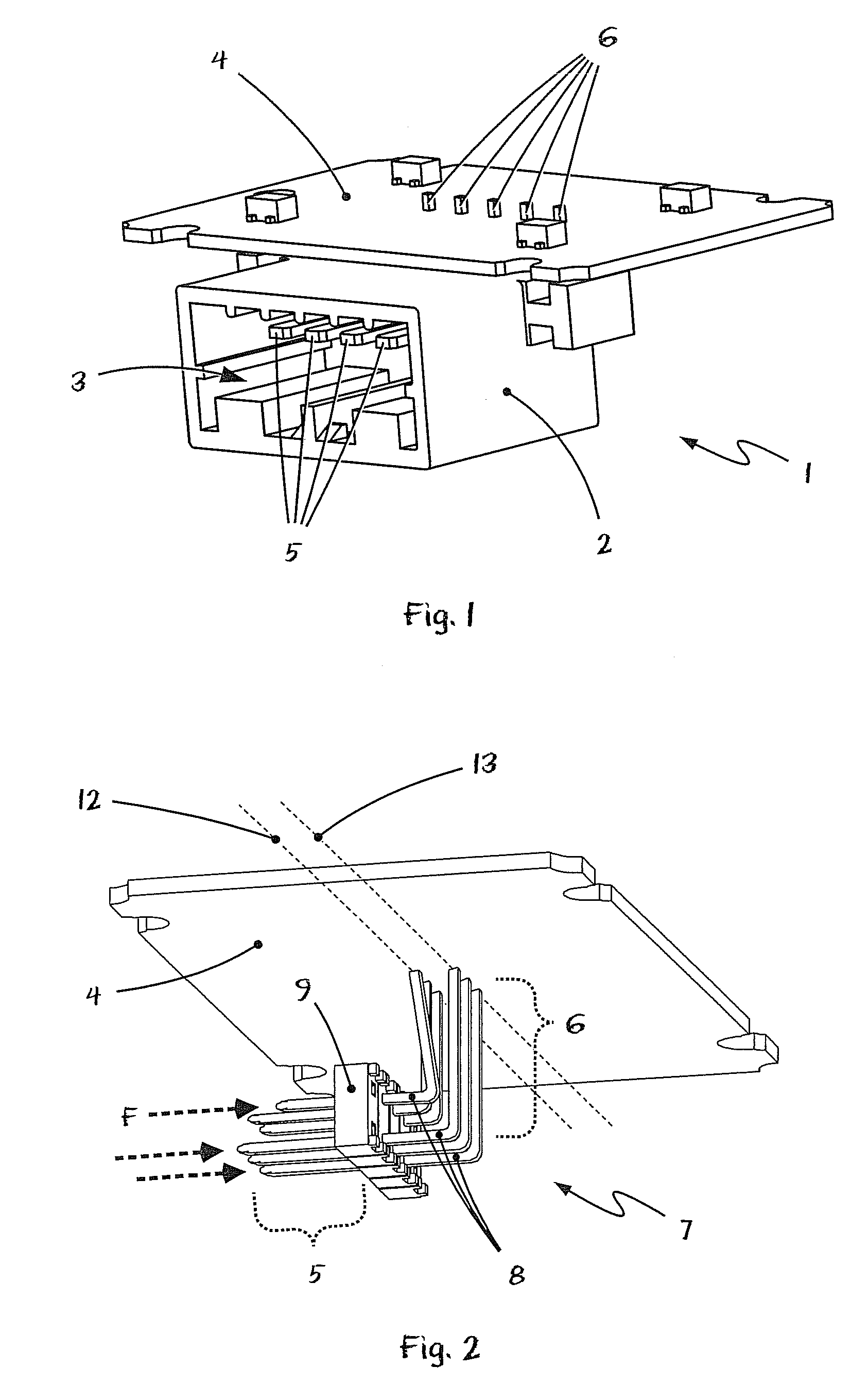
[0031]Referring to the drawings in particular, FIG. 1 shows an isometric view of an angle plug 1 according to the state of the art. The plug pins 5, 6 or the angle pins are firmly extrusion-coated with a housing material 2 in the standard angle plug 1 being shown. The printed circuit board 4 as well as the angle pins with the patch plug-side ends 5 and with the soldered ends 6 passing through the printed circuit board are recognized next to the plug housing 2 with an inner contour 3 for receiving the plug of a cable harness.

[0032]Even though the angle plug 1 shown in FIG. 1 comprises only a single row of angle pins, angle pins with contact or angle pins arranged in two rows are, in principle, likewise formed usually by the extrusion coating of the angle pins with the housing material of the angle plug and thus they correspond, in principle, to the view shown in FIG. 1.

[0033]Angle plugs according to FIG. 1 have the advantage that all contact or angle pins are fixed immovably by the e...


PUM


Abstract

A double-row angle pin connector is provided for a patch plug that has an insertion direction that is parallel to the printed circuit board. The angle pin connector comprises angle pins (8) arranged in two rows in an inner, patch plug-side row (12) as well as in an outer row (13). The angle pins (8) have printed circuit board-side soldered ends (6) and patch plug-side plugged ends (5). The angle pin connector furthermore includes a housing bottom (14) and a housing cover (15) for fixing the angle pins (8). The soldered ends (6) arranged in the patch plug-side row (12) are fixed between the housing bottom (14) and the housing cover (15) by housing support straps (17) bent during the mounting of the housing. The arrangement provides reliably operating multi-pole patch plugs, without angle plugs with a separate extrusion coating, whereby installation space and costs can thus be saved.

Description

CROSS REFERENCE TO RELATED APPLICATIONS[0001]This application is a United States National Phase application of International Application PCT / DE2006 / 001152 and claims the benefit of priority under 35 U.S.C. §119 of German Patent Application DE 10 2005 034 211.6 filed Jul. 19, 2007, the entire contents of which are incorporated herein by reference.FIELD OF THE INVENTION[0002]The present invention pertains to an angle pin connector for an electronic printed circuit board for providing a patch plug parallel to the printed circuit board.BACKGROUND OF THE INVENTION[0003]Angle pin connectors of this class are typically arranged on an electronic board or printed circuit board and are used to establish a connection for receiving a multi-pole plug in the area of the printed circuit board, where the plug or the cable exiting from the plug exits from the angle pin connector in parallel to the surface of the printed circuit board for space reasons in the case being considered.[0004]The connectio...

Claims


Application Information

Patent Timeline
Patent Type & Authority Patents(United States)
IPC IPC(8): H01R12/00H01R12/71
CPCH01R12/712H01R13/4367H01R12/55H01R12/71
Inventor KOHORST, BERTHOLD
Owner ZF FRIEDRICHSHAFEN AG
Why Eureka
Try Eureka