
Actuating device with rotary switch

a technology of rotary switches and actuating devices, which is applied in the direction of mechanical control devices, manual control with single control members, instruments, etc., can solve the problems of limiting the design the type and the location of the operating lever for the transmission of the motor vehicle, and reducing the freedom of the vehicle designer essentially. , to achieve the effect of increasing the design freedom and overcoming the drawbacks of the state of the ar

Active Publication Date: 2015-09-22
ZF FRIEDRICHSHAFEN AG
View PDF15 Cites 13 Cited by
  • Summary
  • Abstract
  • Description
  • Claims
  • Application Information

AI Technical Summary

Benefits of technology

[0012]Against this background, the object of the present invention is to provide a means for the by-wire actuation of a technical system, for example, a speed-change gear, with which the drawbacks of the state of the art can be overcome. In particular, the actuating device shall increase the freedom in designing and arranging the actuating element, and the actuating device shall at the same time also be intuitive and self-explanatory to the operator to the extent possible. One important aspect shall also be the unambiguous tactile feedback of the shifting state and the state of the system during the operation of the corresponding actuating element. Finally, especially the risk of jumping over intermediate positions of the actuating element during shifting in an undesired manner shall be effectively prevented from occurring, and the problem of automatic changes in the state of the system with unchanged position of the actuating element shall be eliminated.
[0015]The design of the actuating element of the actuating device as a rotary switch takes into account especially the fact that no mechanical forces are to be transmitted any longer between the actuating element and the technical system in technical systems that can be actuated electrically or electronically, for example, in shift-by-wire transmissions. This is advantageous because a rotary switch can be embodied with a considerably greater freedom in terms of design and shape and, because of its small space requirement and the optimal ergonomics, which can be adapted to the hand, within easy reach of the operator or driver nearly as desired.
[0017]The blocking device of the rotary switch, which is additionally present in the actuating device according to the present invention, prevents the above-described unintended jumping over of intermediate positions or intermediate switching positions of the rotary switch during switching and leads, moreover, to the possibility of intuitive operation thanks to clear tactile guiding or feedback during the selection of the individual switching positions on the rotary switch.
[0020]According to another, preferred embodiment of the present invention, the rotary switch can be moved, in addition to its rotatability, essentially linearly along at least one other direction of motion. The additional direction of motion is different from the direction of rotary motion, especially in the radial or axial direction relative to the rotary switch. The mobility of the rotary switch along the additional direction of motion can be advantageously used to control additional functions of the same technical system, or for the additional possibility of controlling another device.
[0027]According to another, preferred embodiment of the present invention, provisions are, furthermore, made for both the currently selected operating state of the system or transmission as well as any other selectable operating state to be always displayed at the same location of the display means. It is thus possible to determine the operating state in which the system or transmission currently is by one look, and, moreover, any other operating state of the system or transmission is thus always selected independently from the instantaneous operating state in the same manner or with the same motion process, which is favorable for the possibility of intuitive operation of the actuating device.
[0029]This embodiment of the present invention has especially the advantage that an optionally automatically controlled sinking motion of the rotary switch into the recess of, for example, the center console of a motor vehicle can take place. This property of the actuating device can be used, on the one hand, for design purposes and thus it improves the ergonomics and the comfort in the motor vehicle.

Problems solved by technology

For example, the type and the location of arrangement of the operating lever for a motor vehicle transmission are markedly limited because of the considerable space requirement of such gearshift levers and are limited essentially to the usual accommodation of the gearshift lever in the area of the center console or between the front seats of the motor vehicle.
This is accompanied by limitations in terms of design, and the freedom allowed to the vehicle designer is reduced essentially to the usual locations for mounting the gearshift lever.
The gearshift lever protruding from the center console is not infrequently also disadvantageous in terms of the freedom of motion for the vehicle occupants.
The classical gearshift or selector levels are also often disadvantageous with respect to safety on the motor vehicle.
For example, the clothing of the driver or front-seat passenger may get caught by the gearshift lever during motions and this may compromise the driver's attention to what is happening on the road, or lead even to undesired shifting operations.
Another, frequently likewise safety-relevant problem during the actuation of technical systems by means of classical operating levels is that it may happen relatively easily in case of a plurality of existing shift positions of the operating lever that intermediate positions of the gearshift lever are missed or inadvertently jumped over during shifting.
Even though this may not immediately lead to a safety risk in the case of the example selected, there remains at least the problem that the selector lever is in the “N” position when driving is resumed the next time, and difficulties or lack of clarity could therefore arise when engaging the desired gear.
Finally, the prior-art gearshift levers or automatic selector levers are still also disadvantageous in respect to the behavior in a crash, because such projecting actuating elements may be a source of considerable risks in case of a crash, especially in terms of a possible head impact.

Method used


Image

  • Actuating device with rotary switch
  • Actuating device with rotary switch
  • Actuating device with rotary switch

Examples


first embodiment

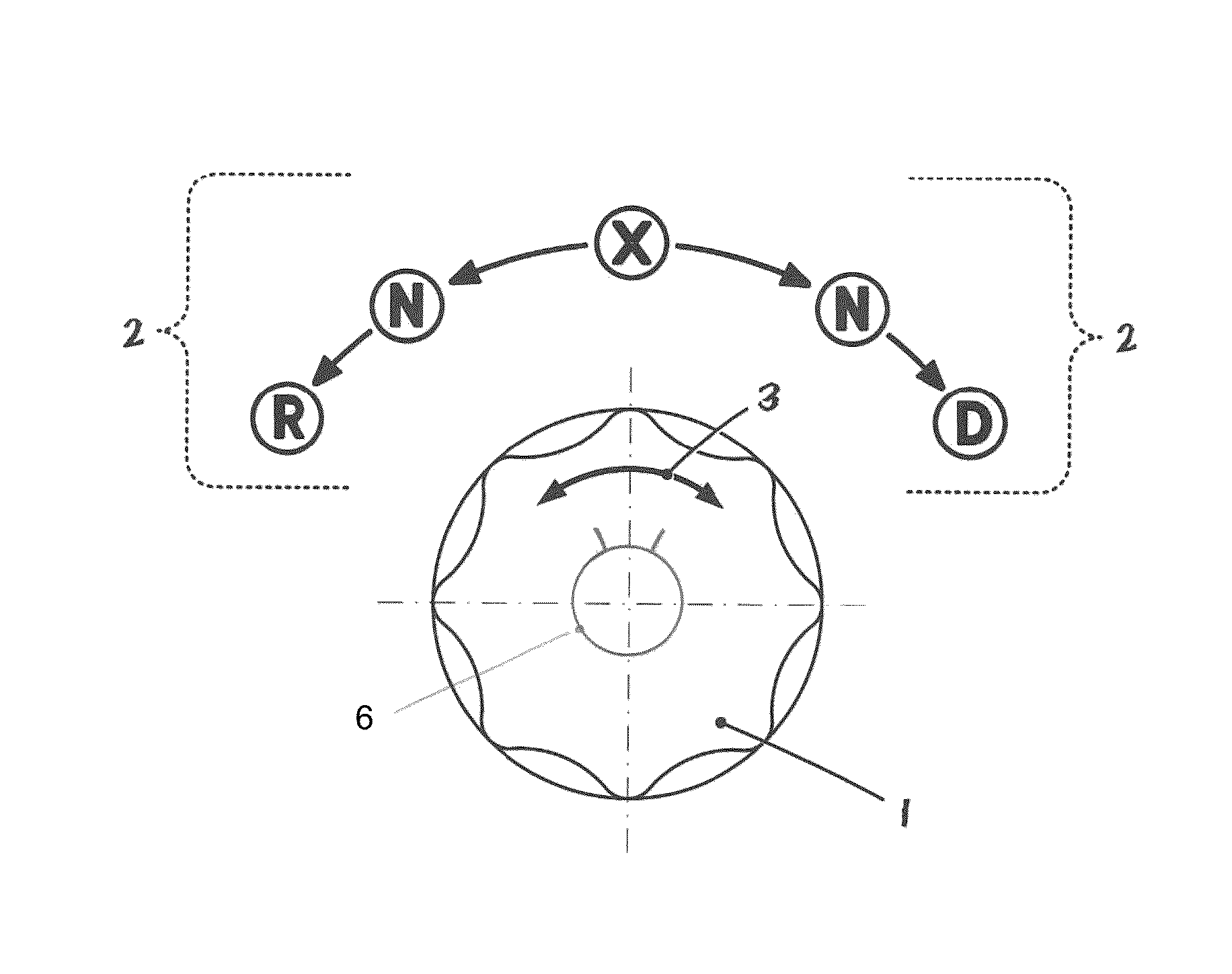
[0039]Referring to the drawings in particular, FIG. 1 shows a schematic view of the rotary switch 1 and the display means 2 of the actuating device according to the present invention. This embodiment is an actuating device for an automatic transmission of a vehicle.

[0040]It can be immediately recognized at first from the view in FIG. 1 that the rotary switch 1 can be turned to the left along its direction of rotary motion 3 in order to select the shifting states “N” or “R” starting from a starting position of the rotary switch 1, which is designated by “X” here, and that the rotary switch 1 can, furthermore, also be turned to the right along its direction of rotary motion 3 in order to select now the shifting state “N” or the shifting state “D.”

[0041]The actuating device is designed here according to the present invention such that the rotary switch 1 will again automatically assume the basic position at “X” after being released from each of the shift positions “N,”“R” and “D.”

[0042...

second embodiment

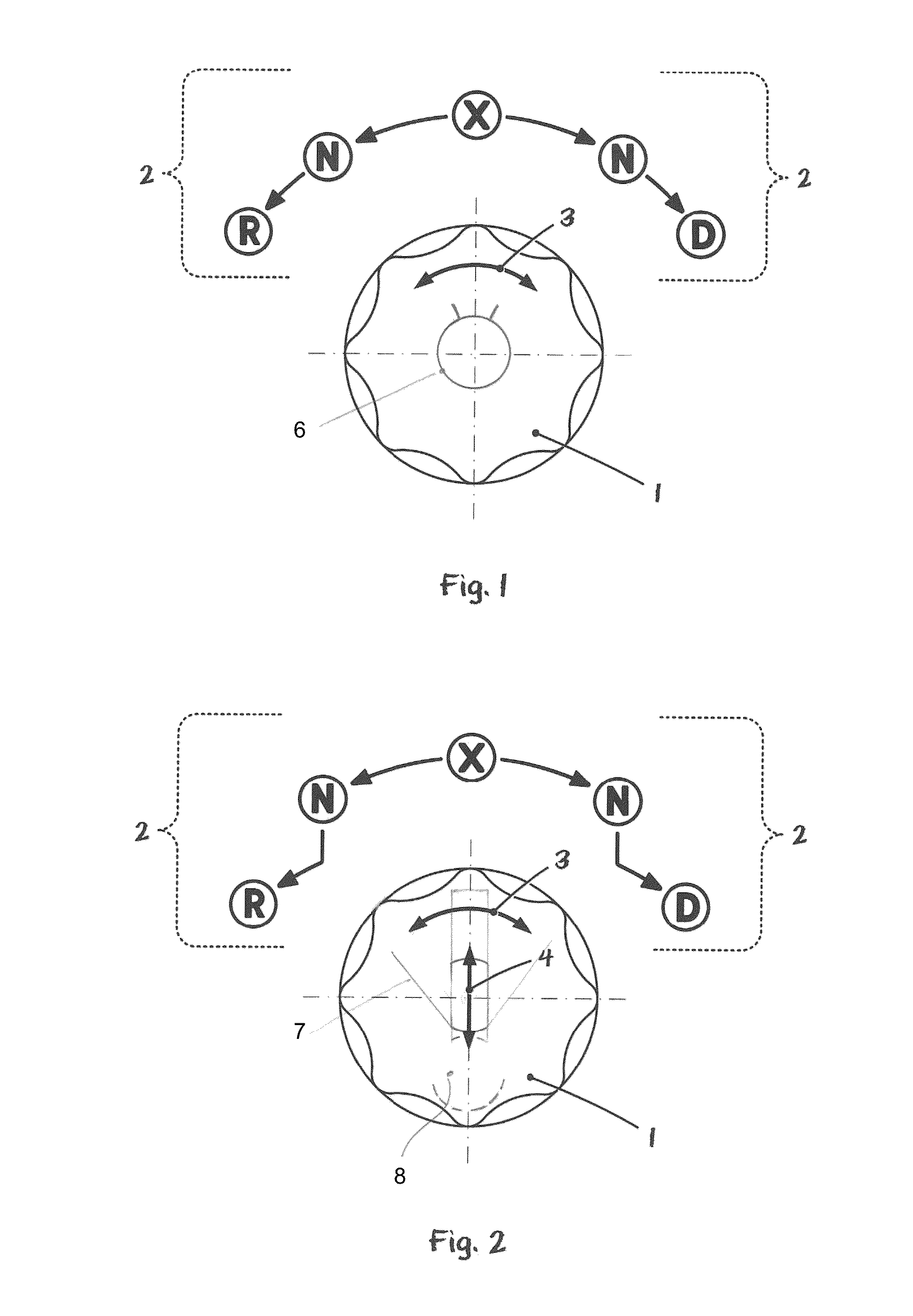
[0045]FIG. 2 shows an actuating device for a vehicle transmission with a rotary switch 1. The embodiment according to FIG. 2 differs from the embodiment according to FIG. 1 especially in that the rotary switch 1 according to FIG. 2 can also be displaced, moreover, in a radial direction 4 or along the plane of the vehicle console (not shown), besides the rotary motion 3 about its axis. The blocking device of the actuating device according to FIG. 2 also differs in this connection from the blocking device of the actuating device according to FIG. 1.

[0046]The view in FIG. 2 can, furthermore, also be interpreted such that the rotary switch 1 according to FIG. 2 can also be pushed or pulled in the axial direction, in other words, displaced along its axis of rotation—instead of along the radial direction 4—besides the rotary motion 3 about its axis.

[0047]To engage one of the two gears “R” or “D” with the rotary switch 1 according to FIG. 2 starting from the starting position “X” or starti...

fourth embodiment

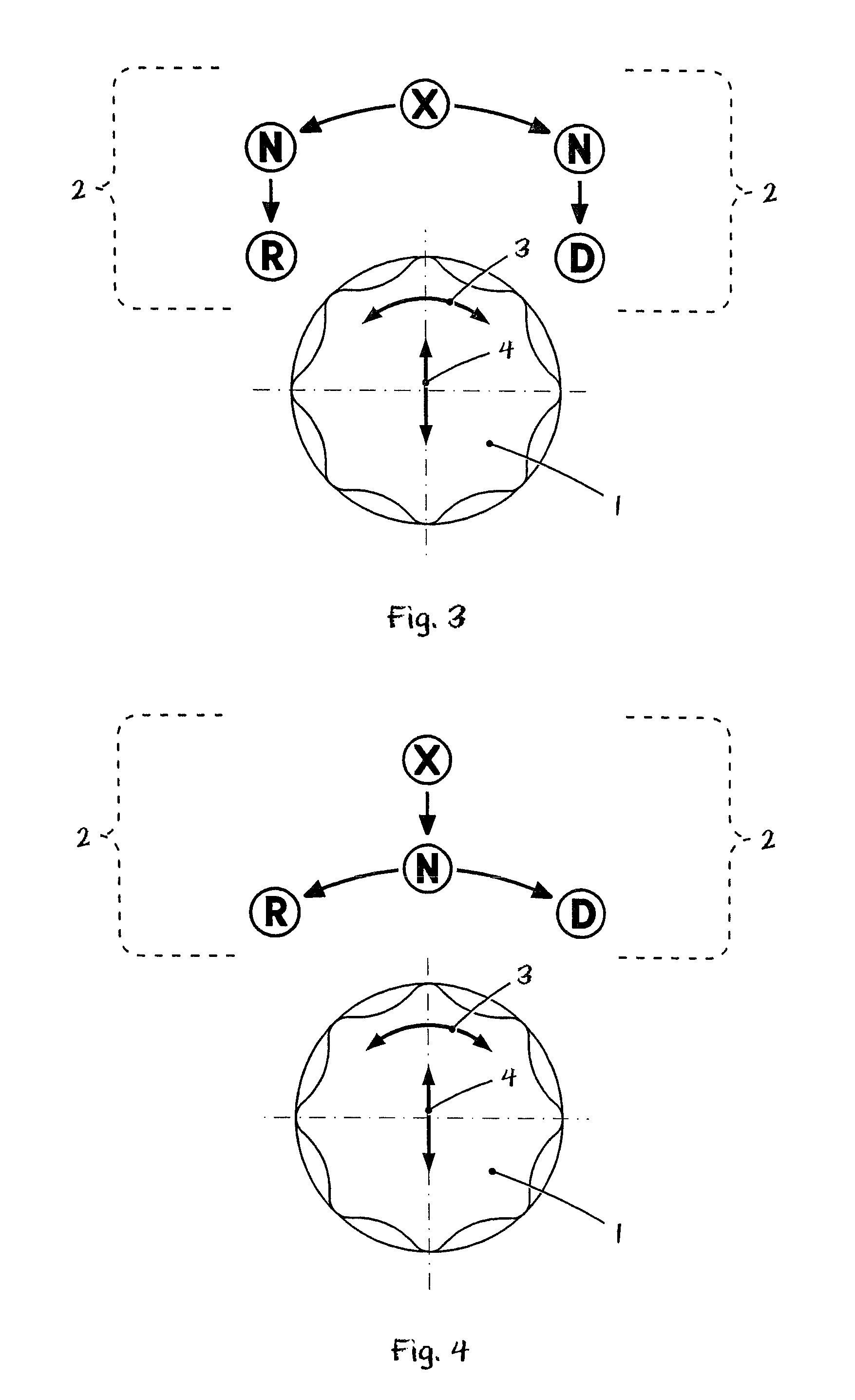
[0051]an actuating device for a vehicle transmission with a rotary switch is shown in FIG. 4. This embodiment differs from the preceding embodiments especially in that only one switching position of the rotary switch 1 is associated with the neutral position “N” of the vehicle transmission, as well as in that both the neutral position “N” of the vehicle transmission and the display of the instantaneously engaged gear “X” are associated with the initial rotation position of the rotary switch 1.

[0052]The selection of one of the gears “R” or “D” thus takes place in the case of the embodiment according to FIG. 4 such that the rotary switch 1 is first displaced starting from its starting position or basic position linearly downward relative to the drawing along its direction of radial motion 4 (or, for example, it is pushed in along its axial direction in another embodiment). As a consequence of the blocking means of the actuating device, which comprises a shift gate, it is subsequently ...


PUM


Abstract

An actuating device is provided that includes an actuating element (1) with at least three switching positions. The actuating device (1) can be deflected starting from its basic positions at least in one direction into an intermediate switching position for selecting an operating state of the technical system. For selecting at least one other operating state of the technical system, the actuating element (1) can be deflected, starting from an intermediate switching position, into at least one other switching position that is located farther away from the basic position. The undesired jumping of the actuating element over intermediate switching positions, during switching, is effectively prevented from occurring. An intuitively detectable tactile feedback of the switching state of the actuating element or of the state of the system is provided.

Description

CROSS REFERENCE TO RELATED APPLICATIONS[0001]This application is a United States National Phase application of International Application PCT / DE2005 / 002008 and claims the benefit of priority under 35 U.S.C. §119 of German Patent Application DE 10 2004 054 264.3 filed Nov. 9, 2004, the entire contents of which are incorporated herein by reference.FIELD OF THE INVENTION[0002]The present invention pertains to a means for actuating a technical system, especially for a shift-by-wire speed-change gear, in which the actuating device comprises an actuating element with at least three shift positions including a basic position, wherein the actuating element can be deflected from the basic position at least in one direction into an intermediate switching position and can be deflected from the intermediate switching position into at least one other switching position located farther away from the basic position than the intermediate switching position.BACKGROUND OF THE INVENTION[0003]The gear p...

Claims


Application Information

Patent Timeline
Patent Type & Authority Patents(United States)
IPC IPC(8): F16H59/08G05G5/05G05G5/03G05G1/08B60K37/06G05G5/12G05G5/00G05G9/02F16H61/22F16H59/02F16H59/04
CPCF16H59/08B60K37/06G05G1/087G05G5/005G05G5/03G05G5/05G05G5/12G05G9/02B60K2350/102F16H61/22F16H2059/0295F16H2059/048F16H2059/081Y10T74/20474B60K2370/158B60K2370/126
Inventor MEYER, JOERGGIEFER, ANDREAS
Owner ZF FRIEDRICHSHAFEN AG
Learn More