
Load-sensing system with at least one ball and socket joint

a technology of at least one ball and socket joint, applied in the direction of couplings, instruments, force/torque/work measurement apparatus, etc., can solve the problems of unsuitability of prior-art load-sensing means for determining more complex load situations, and the benefit of this prior-art load-sensing means is limited, so as to achieve a simple and reliable manner. , the effect of great freedom

Inactive Publication Date: 2009-06-30
ZF FRIEDRICHSHAFEN AG
View PDF14 Cites 2 Cited by
  • Summary
  • Abstract
  • Description
  • Claims
  • Application Information

AI Technical Summary

Benefits of technology

The present invention provides a load-sensing system or a ball and socket joint with a load-sensing means that can determine loads and torques in a simple and reliable manner. The load-sensing system makes use of an evaluating means that can output the signals of the load-sensing means as a load vector or a combination of a load vector and a torque vector in a cartesian coordinate system. The load-sensing system can be calibrated and can be used in various applications, such as in motor vehicles. The technical effects of the present invention include improved accuracy in load and torque sensing, simplified and reliable load-sensing design, and the ability to determine loads in all directions.

Problems solved by technology

However, the benefit of this prior-art load-sensing means is limited.
The prior-art load-sensing means is thus unsuitable for determining more complex load situations, as they occur, for instance, on larger assembly units or on the motor vehicle as an overall system.

Method used


Image

  • Load-sensing system with at least one ball and socket joint
  • Load-sensing system with at least one ball and socket joint
  • Load-sensing system with at least one ball and socket joint

Examples


Embodiment Construction

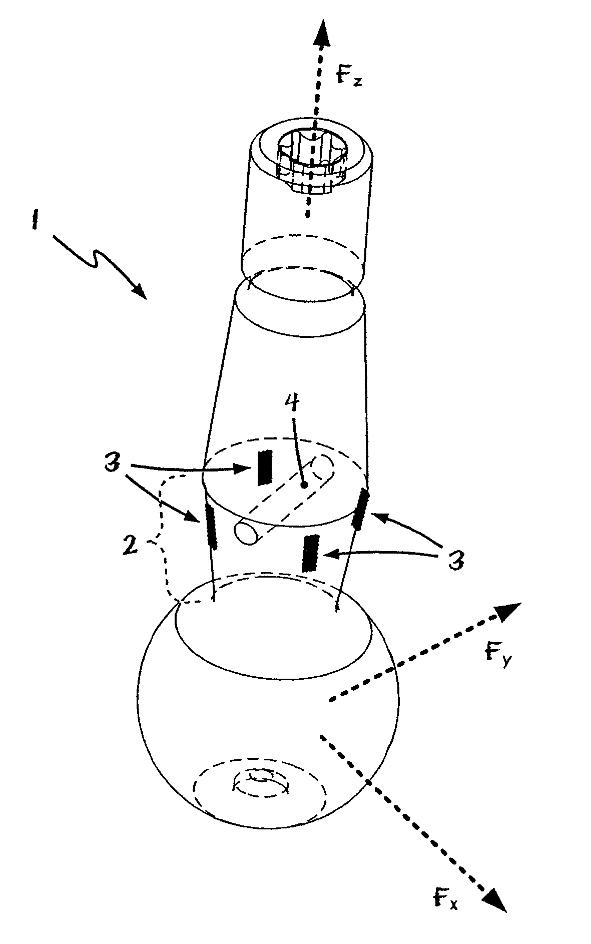
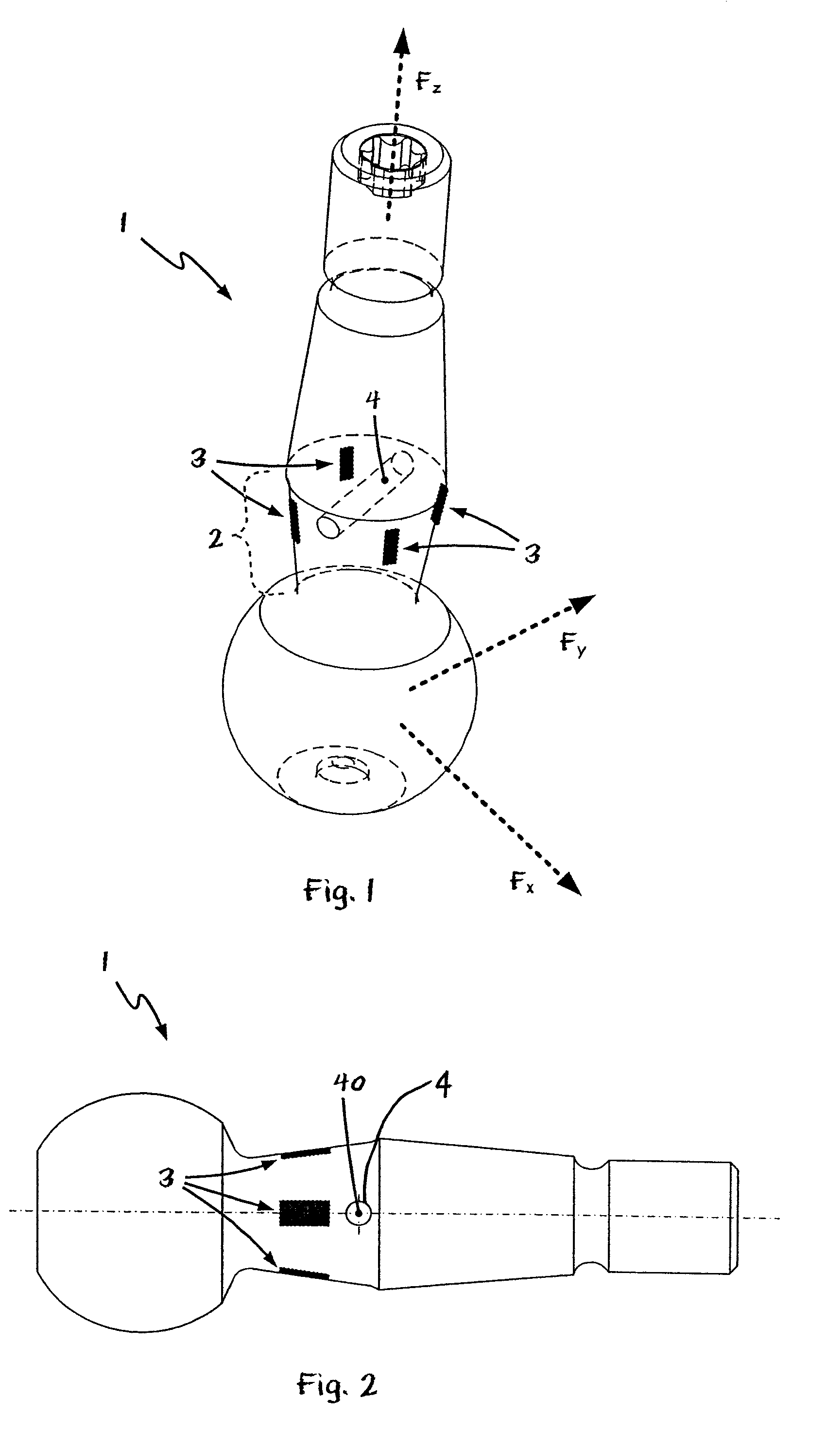
[0036]Referring to the drawings in particular, FIG. 1 shows a schematic isometric view of the ball pivot 1 of a ball and socket joint 50, for a load-sensing system 100 according to the present invention.

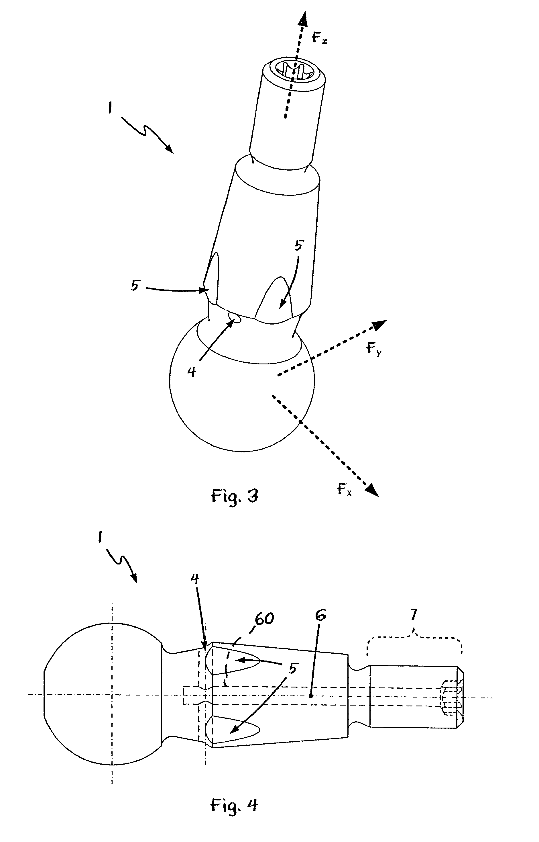
[0037]With the exception of the wire strain gauge 3 arranged in the neck area 2 of the ball pivot 1 as well as with the exception of the cross hole 4, the ball pivot 1 corresponds, unchanged, to a standard ball pivot of a ball and socket joint. This means that a ball and socket joint (50) present, for instance, in the area of the wheel suspension of a motor vehicle, can already be used for the load-sensing system according to the present invention with extremely slight and hence inexpensive modifications.

[0038]Four wire strain gauges 3 are arranged distributed on the circumference in the area of the neck 2 of the ball pivot in the exemplary embodiment shown in FIG. 1 in such a way that two adjacent wire strain gauges each form an angle of 90°. Furthermore, the longitudinal axis of th...


PUM

PropertyMeasurementUnit
angleaaaaaaaaaa
areaaaaaaaaaaa
torqueaaaaaaaaaa

Abstract

A load-sensing system is provided with at least one ball and socket joint and a ball and socket joint for load sensing is provided. The ball and socket joint of the load-sensing system has a joint housing, in which the joint ball of a ball pivot (1) can be received in a slidingly movable manner. The ball pivot (1) comprises a shaft area and a joint ball, a load-sensing means (3) being arranged in the shaft area of the ball pivot. The load-sensing system is characterized according to the present invention by an evaluating means, which is set up such that the signals of the load-sensing means (3) are output as a vector in a cartesian coordinate system. The load sensing makes it possible to reliably determine the operating or load state not only of individual components but rather of entire assembly units of a motor vehicle and with which the vehicle dynamics can be adjusted.

Description

CROSS REFERENCE TO RELATED APPLICATIONS[0001]This application is a United States National Phase application of International Application PCT / DE2005 / 001900 and claims the benefit of priority under 35 U.S.C. § 119 of German Patent Application 10 2004 051 504.2 filed Oct. 21, 2004, the entire contents of which are incorporated herein by reference.FIELD OF THE INVENTION[0002]The present invention pertains to a load-sensing system with at least one ball and socket joint for sensing loads and / or torques, for example, in the area of the chassis or the wheel suspension of motor vehicles. Furthermore, the present invention pertains to a ball and socket joint with a load-sensing feature, especially for a load-sensing system according to the present invention.BACKGROUND OF THE INVENTION[0003]Load-sensing means of the type mentioned in the introduction are used, for example, but by no means exclusively, in motor vehicles in order to make it possible to reliably measure the loads or torques occu...

Claims


Application Information

Patent Timeline
Patent Type & Authority Patents(United States)
IPC IPC(8): G01L3/02
CPCB60G7/005B60G17/019F16C11/0619B60G2204/11B60G2204/416Y10T403/32737B60G2400/61B60G2400/64B60G2401/12B60G2400/60F16C2326/05F16C11/0604F16C17/24G01L5/00F16C11/06
Inventor STEINKAMP, UWEKORNHAGE, MARTINHEGEMANN, ALFONS
Owner ZF FRIEDRICHSHAFEN AG
Learn More