Silt fencing system

a technology of silt fences and panels, applied in the field of fences, can solve the problems of limiting the transportability of fences, difficult installation of fences, and inefficient silt fences, and achieve the effects of convenient transportation, convenient disassembly and assembly of fence sections, and easy bend or flex

Inactive Publication Date: 2010-07-27
BERENYI GARY
View PDF23 Cites 11 Cited by
  • Summary
  • Abstract
  • Description
  • Claims
  • Application Information

AI Technical Summary

Benefits of technology

[0009]To assemble the fencing section, front ends of the rods are inserted into slots, adapted to hold the ends of rods, of a male or female framing member. The rods are then guided through corresponding sleeve supports in the fencing material. Front ends of the rods are inserted into slots in the remaining male or female member. The fencing section may be disassembled by pulling the rods out of the either the male or female member so that the rods are no longer in the sleeve supports. Removing the rods allows the fencing material attached to the male member and female member to be compressed and easily transported.
[0010]The rods are collapsible, i.e., the rods can readily bend or flex and re-assume its original position. The collapsibility of the rods allows the fence to be driven over by a truck and re-assume its original form once the truck has passed.
[0011]In one preferred embodiment of the invention, the rods are telescopic. When the rods are telescopic, the fencing section may be kept in an assembled state and compressed to allow for easy transportation.
[0012]The design of the fencing section enables a fence, with a length longer than the fencing section, to be easily assembled. The male member of the fencing section is inserted into a second female member of a second fencing section, creating a fence with a length of two fencing sections. The process may be continued until a desired length is reached.

Problems solved by technology

While appearing simple to construct, this type of silt fence is actually very inefficient and costly.
In addition, mainly because the fencing material will tend to tear when attempting to detach it from the stakes, these types of fencing arrangements are generally designed for one-time use.
With this construction, Shea's invention requires post units driven into the ground, making the fence difficult to install and limiting its transportability.
However, the barrier is often replaced because the foam deteriorates and it develops a smell.
When the barrier needs to be replaced, the whole barrier needs to be replaced, increasing the costs to maintain the barrier.
In addition, since the foam barrier is one piece and not very compressible, the barrier is not easily storable.

Method used


Image

  • Silt fencing system
  • Silt fencing system
  • Silt fencing system

Examples


Embodiment Construction

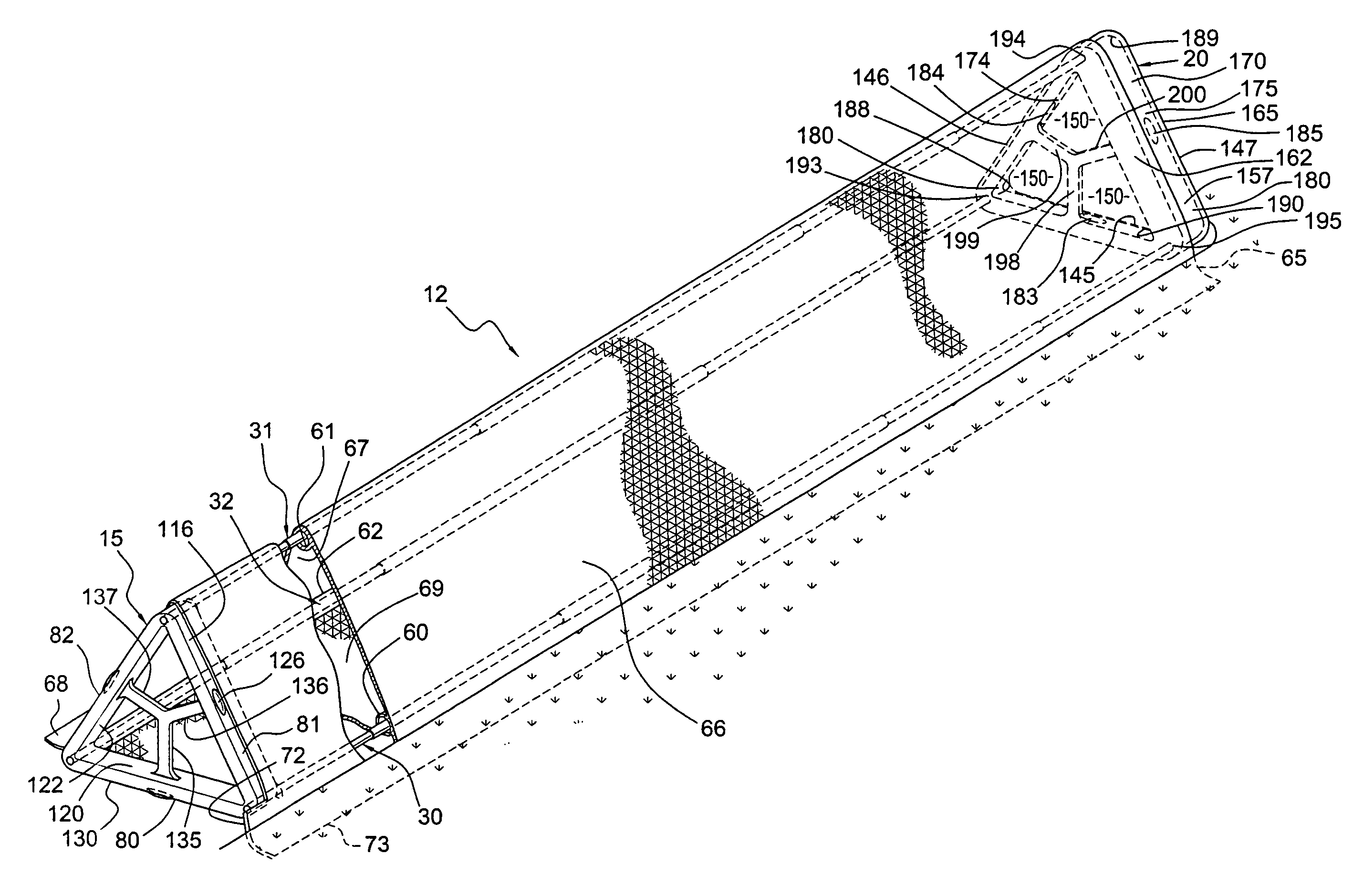
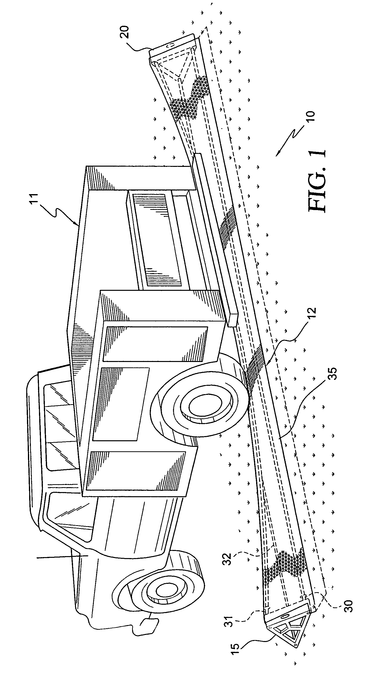
[0021]With initial reference to FIG. 1, a silt fencing system 10 constructed in accordance with the present invention is shown being driven over by a truck 11 leaving a construction site. Silt fencing system 10 includes a fencing section 12 that is collapsible as shown. Fencing section 12 comprises a triangularly shaped first framing member or male member 15, a triangularly shaped second framing member or female member 20, tension rods 30-32 and a fencing material 35. As shown in FIG. 1, tension rods 30-32 are collapsible, allowing a truck to drive over fencing section 12 without destroying fencing section 12. It is preferred that tension rods 30-32 are of such a length that gives flexibility to fencing section 12. The length of tension rods 30-32 are able to bend without affecting male member 15 and female member 20, while fencing material 35 drops with tension rods 30-32. Once the truck has passed, fencing section 12 re-assumes its original form.

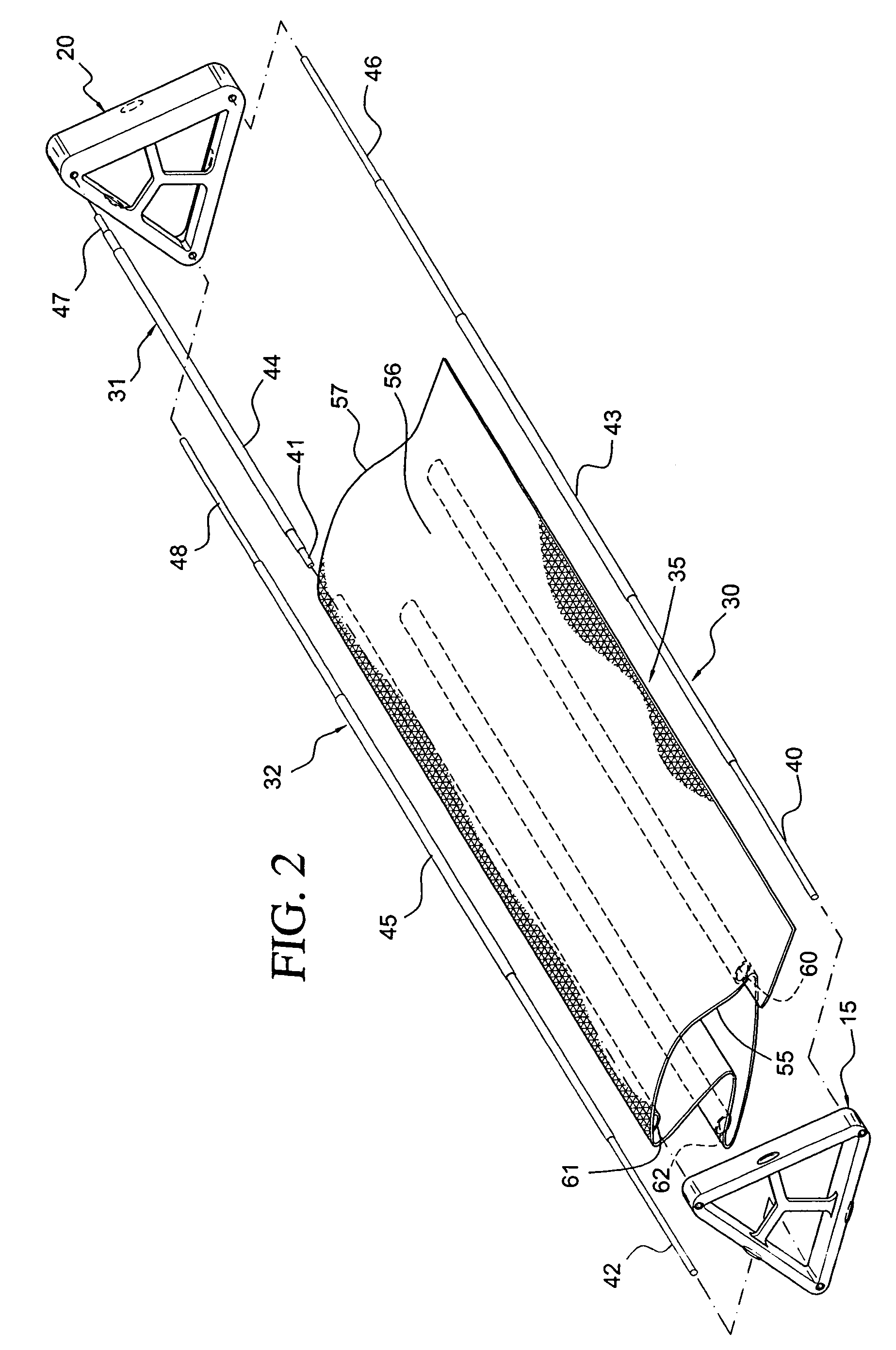
[0022]Referring to FIG. 2, tension ...


PUM


Abstract

A transportable and reusable silt fencing system for use at a construction site to prevent sediment and soil erosion comprises tension rods, a male section, a female section, and a fencing material having sleeve supports for the rods to slide in and support the fencing material. The tension rods are collapsible. The rods collapse when a truck drives over the fence, but re-assume their original form once the truck has passed. If a fence longer than the fencing section is required, additional fencing sections may be attached by connecting a male section of one fence section with the female section of another fence section.

Description

BACKGROUND OF THE INVENTION[0001]1. Field of the Invention[0002]The present invention pertains to the art of fences and, more particularly, silt fencing for preventing soil erosion.[0003]2. Discussion of the Prior Art[0004]Silt fences are often used as barriers to sediment, particularly in connection with preventing soil erosion at construction sites. In fact, many counties in the United States have enacted ordinances requiring the use of erosion control fencing at both residential and commercial building locations. Conventional silt fences are made by driving wooden stakes into the ground and stapling a partially buried, flexible plastic fencing material to the wooden stakes. While appearing simple to construct, this type of silt fence is actually very inefficient and costly. For instance, care must be taken when driving the wooden stakes into the ground as telephone, cable and other wires may be present below the surface. In addition, mainly because the fencing material will tend ...

Claims


Application Information

Patent Timeline
Patent Type & Authority Patents(United States)
IPC IPC(8): E02B7/00
CPCE01F7/025
Inventor BERENYI, GARY
Owner BERENYI GARY
Why Eureka
Try Eureka