General diffractive optics method for expanding an exit pupil

a general diffractive and optics technology, applied in optics, instruments, diffraction gratings, etc., can solve the problem that the display no longer qualifies as an ned, and achieve the effect of improving the optical coupling

Active Publication Date: 2010-07-27
MAGIC LEAP INC
View PDF20 Cites 153 Cited by
  • Summary
  • Abstract
  • Description
  • Claims
  • Application Information

AI Technical Summary

Problems solved by technology

Thus, such a display no longer qualifies as an NED, for obvious reasons.

Method used


Image

  • General diffractive optics method for expanding an exit pupil
  • General diffractive optics method for expanding an exit pupil
  • General diffractive optics method for expanding an exit pupil

Examples


Embodiment Construction

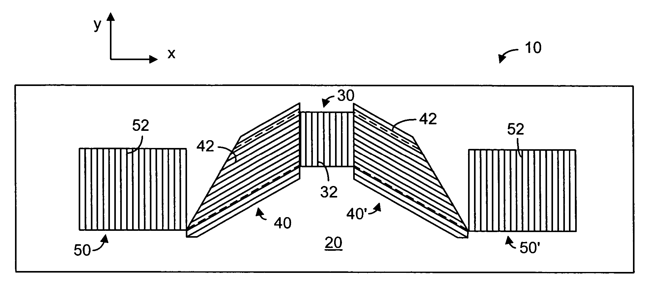
[0065]In the exit pupil extender (EPE) 10, according to the present invention, has a substrate 20 made of an optical material. On the substrate 20, there are one input optical element 30 and one or two exit optical elements 50, as shown in FIG. 2. The EPE 10 also has one or two intermediate optical couplers 40, 40′ each disposed between the input optical element 30 and one of the exit optical elements 50, 50′. The couplers 40, 40′ serve as exit pupil extending components. The optical elements 30, 50, 50′ and the couplers 40, 40′ are diffractive optical elements (DOEs), for example. Each of the DOEs has a plurality of grating lines for diffraction purposes. As shown, the optical element 30 has a plurality of grating lines 32; the optical element 40 (40′) has a plurality of grating lines 42 and the optical element 50 (50′) has a plurality of grating lines 52.

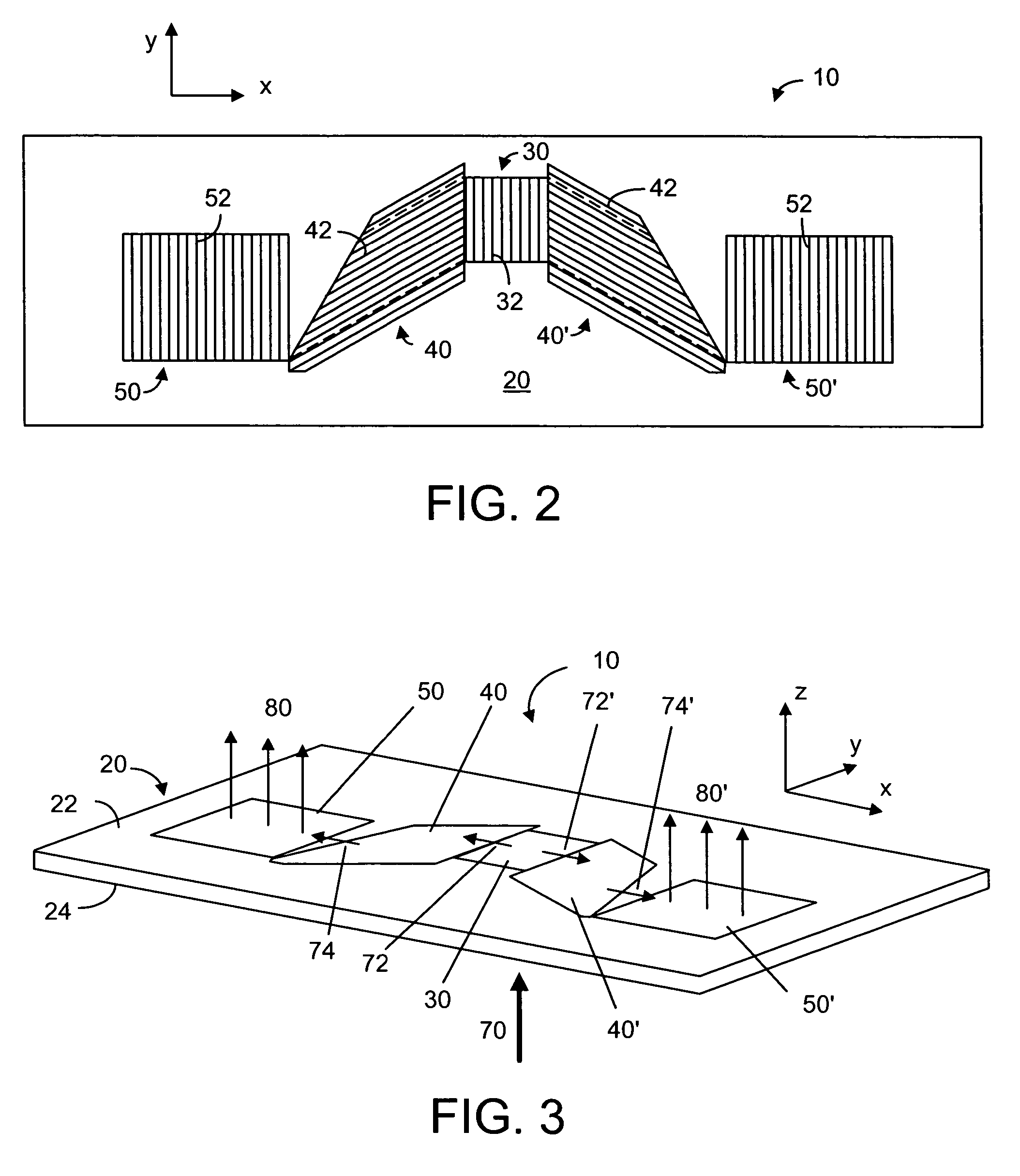
[0066]FIG. 3 is an isometric view showing the relationship between an input beam 70 and two exit beams 80, 80′. As shown, the su...


PUM


Abstract

An exit pupil extender with one input optical element and two exit optical elements disposed on different sides of the input optical element. The exit pupil extender also comprises two intermediate diffractive optical couplers, each disposed between the input optical element and one exit optical element. The couplers serve as exit pupil extending components. The grating lines of the couplers are at substantially a 60-degree angle from that of the optical elements in order to optimize the exit pupil extending efficiency. This invention further describes a general diffractive optics method that uses a plurality of diffractive elements on an optical substrate for expanding the exit pupil of a display of an electronic device for viewing. The system can support a broad range of rotations angles (e.g., 0<ρ<70°) and corresponding conical angles and remains geometrically accurate.

Description

PRIORITY AND CROSS-REFERENCE TO RELATED APPLICATION[0001]This application is a continuation in part of and claims priority from U.S. patent application Ser. No. 11 / 011,481, filed on Dec. 13, 2004 now abandoned.TECHNICAL FIELD[0002]The present invention relates generally to a display device and, more specifically, to a general diffractive optics method that uses a plurality of diffractive elements for expanding the exit pupil of a display for viewing.BACKGROUND ART[0003]While it is a common practice to use a low-resolution liquid-crystal display (LCD) panel to display network information and text messages in a mobile device, it is preferred to use a high-resolution display to browse rich information content of text and images. A microdisplay-based system can provide full color pixels at 50-100 lines per mm. Such high-resolution is generally suitable for a virtual display. A virtual display typically consists of a microdisplay to provide an image and an optical arrangement for manipul...

Claims


Application Information

Patent Timeline
Patent Type & Authority Patents(United States)
IPC IPC(8): G03H1/00G03H1/22
CPCG02B27/4205G02B27/0081
Inventor LEVOLA, TAPANI
Owner MAGIC LEAP INC
Why Eureka
Try Eureka