Scrapping plate for a cotton picker

a technology of scraping plate and cotton picker, which is applied in the field of scraping plate, can solve the problems of less than optimal picking performance of such non-conventional scraping bars, excessive distance between the leading or lagging spindle path and the respective lagging and leading surfaces of the pocket, etc., and achieve optimal spacing and optimal picking efficiency. , the effect of maximizing the efficiency of picking

Active Publication Date: 2010-08-03
DEERE & CO
View PDF4 Cites 6 Cited by
  • Summary
  • Abstract
  • Description
  • Claims
  • Application Information

AI Technical Summary

Benefits of technology

[0005]It is a further object to provide an improved scrapping plate for use with spindle bars having non-aligned spindle paths for optimizing picking efficiency. It is yet another object to provide a scrapping plate that maintains proper clearance for each row of spindles as the spindles pass the plate.
[0006]A scrapping plate includes alternating offset pockets or channels with offset positions relative each other to accommodate the different spindle paths associated with spindle bars having spindles which are non-aligned or offset at an angle relative to each other. The offset pockets or channels provide optimal spacing between the different spindle paths and the plate to ensure maximum contact between the spindle and the cotton boll. By maintaining proper positioning and clearance between the spindle paths and the pockets of the scrapping plate, picking efficiency is maximized. The offset also gives smoother flow and reduced peak loads in the power train.

Problems solved by technology

Use of prior art style scrapping plates wherein pockets are of equal size and of uniform position results in less than optimum picking performance with such non-conventional spindle bars.
The prior art scrapping plate must be centered between the two spindle paths, which results in excessive distances between the leading or lagging spindle path and the respective lagging and leading surfaces of the pockets.

Method used


Image

  • Scrapping plate for a cotton picker
  • Scrapping plate for a cotton picker
  • Scrapping plate for a cotton picker

Examples


Embodiment Construction

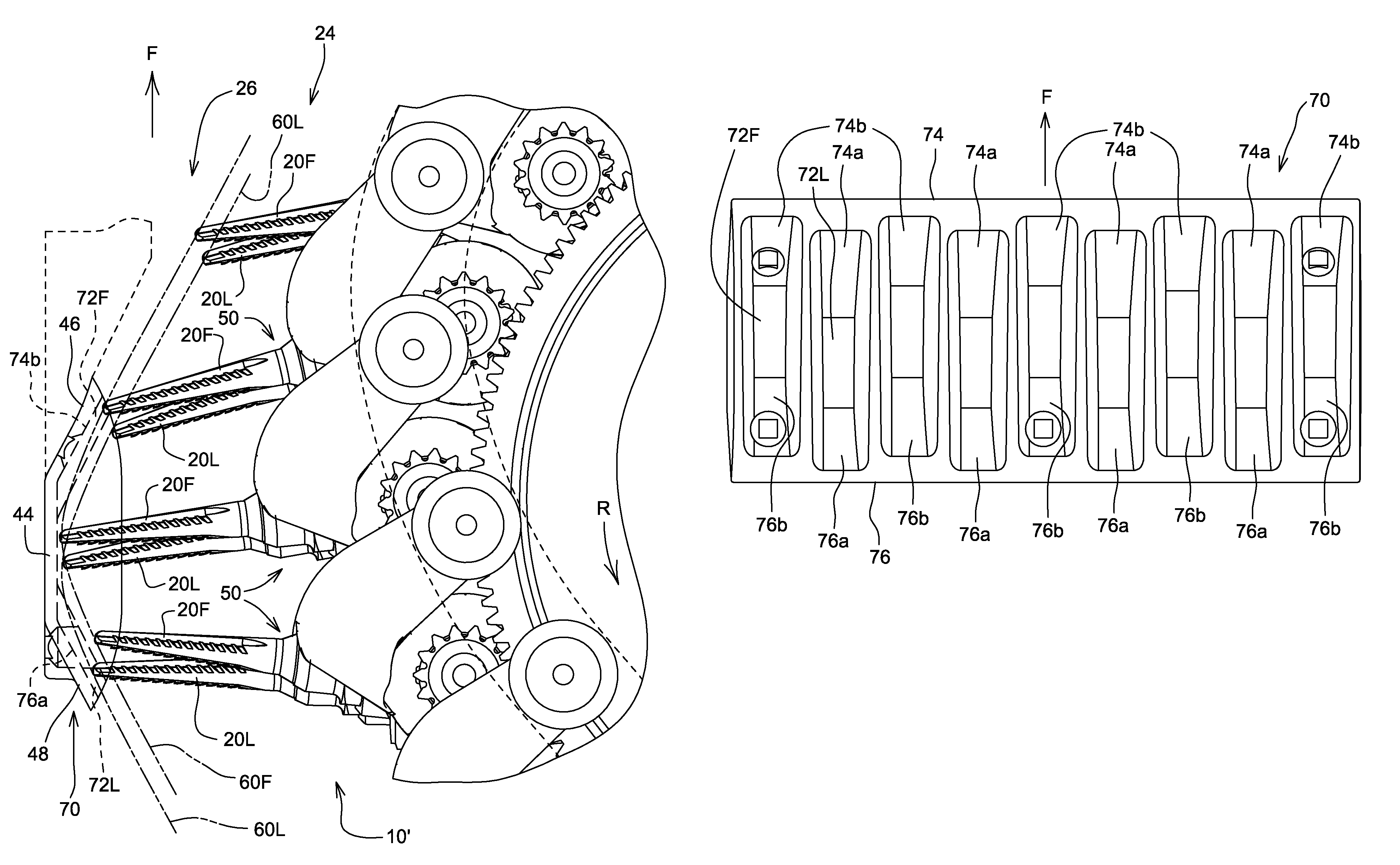
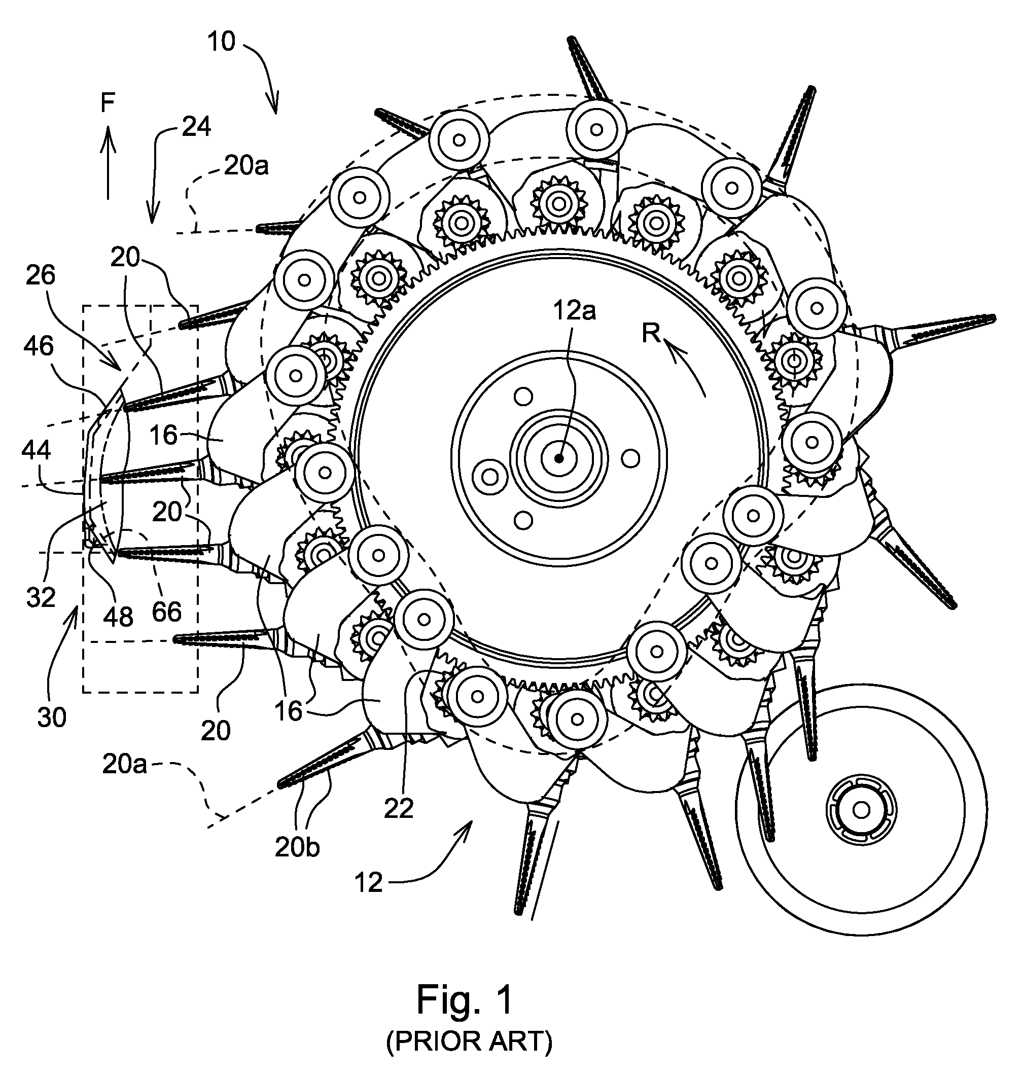
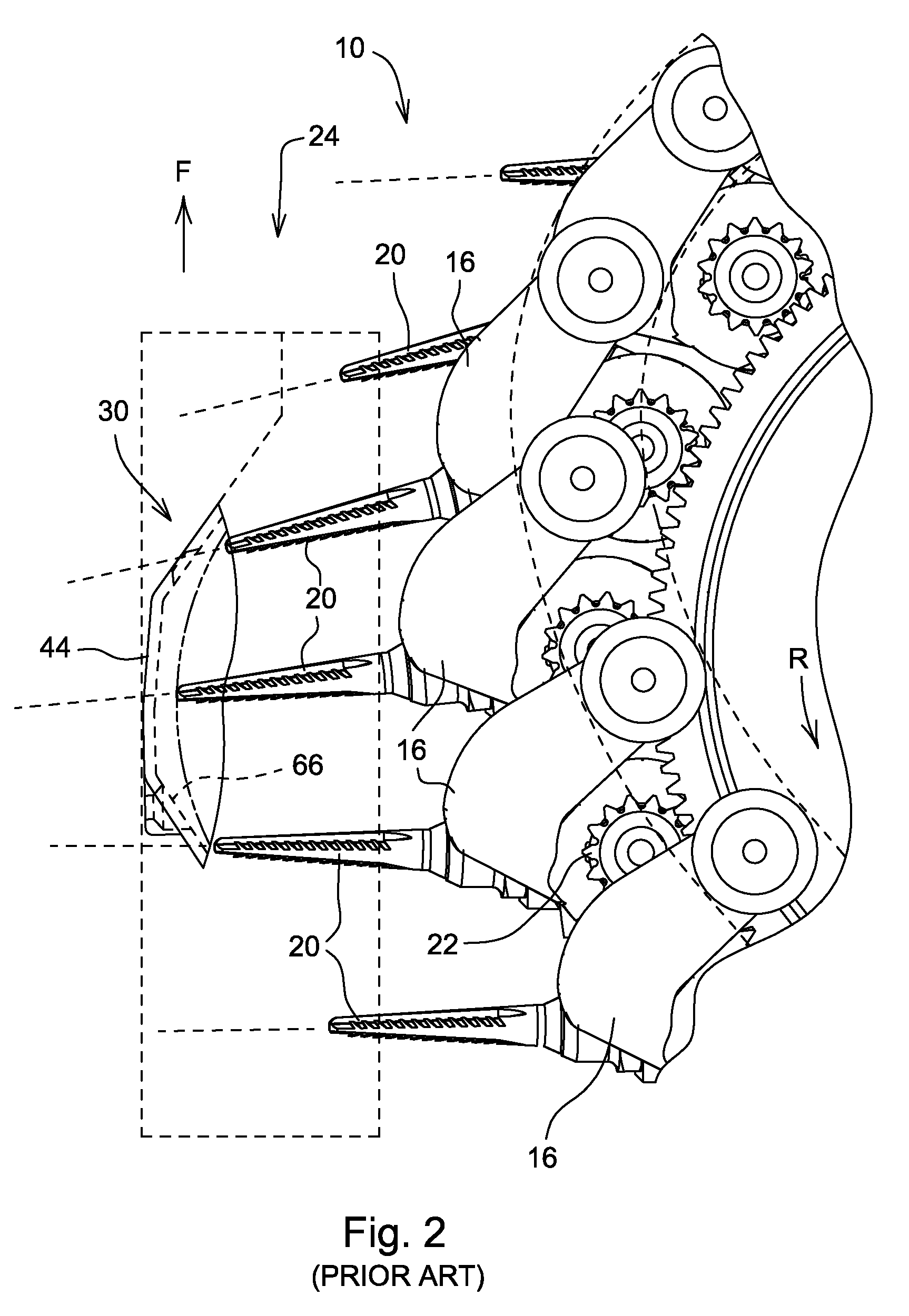
[0016]Referring to FIG. 1 (prior art) therein is shown a portion of a cotton picker row unit 10 having a rotating picker drum 12 with upright picker bars 16. A plurality of vertically aligned cotton picker spindles 20 are mounted for rotation about spindle axes 20a by a conventional spindle drive 22. As the row unit 10 is moved in the forward direction F, a row of cotton plants enters a crop receiving area 24 and is engaged by the rotating spindles 20 in a picking zone 26. The drum 12 is rotated in direction R about a drum axis 12a at a speed synchronized to the row unit forward speed so that the rearward speed of the spindles 20 is approximately equal to the forward speed of the row unit, and the velocity of the spindles in the picking zone 26 relative to the cotton plants approaches zero. The rotating spindles 20 include barbed areas 20b that engage and snag the cotton bolls and remove the cotton from the plants.

[0017]To increase picking efficiency, a scrapping plate 30 is provide...


PUM


Abstract

A scrapping plate includes alternating channels or pockets offset in the fore-and-aft direction relative each other to accommodate the different spindle paths associated with spindle bars having spindles which are non-aligned or offset at an angle relative to each other. The offset pockets provide optimal spacing between the different spindle paths and the plate to ensure maximum contact between the spindle picking ends and the cotton bolls to maximize overall picking efficiency. In one embodiment, the pockets are identical but offset in the spindle travel direction from each other and include leading and trailing ends which are angled or curved for conforming closely to the different spindle paths.

Description

FIELD OF THE INVENTION[0001]The present invention relates generally to spindle-type cotton pickers and, more specifically, to scrapping plates for improving the picking efficiency of such pickers.BACKGROUND OF THE INVENTION[0002]Cotton pickers typically have picker bars with a number of uniformly spaced spindles orientated vertically in a straight line. The spindles project into the plant row and are rotated to remove cotton from the plants. The rearward velocity of the spindles is synchronized with the forward speed of harvester to generally provide zero relative velocity between the spindles and the cotton plants. To help assure contact with cotton bolls intermediate adjacent spindles, scrapping plates are placed adjacent the spindles in the picking zone to slow the intermediate bolls and force them into contact with the next spindles. Scrapping plates of the type described in commonly assigned U.S. Pat. No. 6,591,597 contain pockets of a common profile aligned in a single straigh...

Claims


Application Information

Patent Timeline
Patent Type & Authority Patents(United States)
IPC IPC(8): A01D46/16
CPCA01D46/18
Inventor OSTERMEIER, CHARLES FREDERICKGOERING, KEVIN JACOB
Owner DEERE & CO
Why Eureka
Try Eureka