Start-up circuit for bandgap reference

a bandgap reference and start-up circuit technology, applied in the direction of electric variable regulation, process and machine control, instruments, etc., can solve the problems of unstable approach, lowest possible reference voltage, unpredictable start-up characteristics, etc., and achieve the effect of stable operating sta

Active Publication Date: 2010-08-03
MARVELL ASIA PTE LTD
View PDF9 Cites 26 Cited by
  • Summary
  • Abstract
  • Description
  • Claims
  • Application Information

AI Technical Summary

Benefits of technology

[0013]By virtue of this operation, since current is sampled through the diode itself, a stable start-up condition is ensured since current injection will continue until current through the diode is higher than the pre-designated low value. The bandgap reference consequently achieves a stable operating state since the circuit is correctly driven until the diodes achieve the conduction that is needed to achieve PTAT and CTAT operation of the diode / resistor networks.

Problems solved by technology

One drawback of conventional bandgap reference circuitry is that, when supplying a reference voltage, the lowest possible reference voltage is limited to a low value of approximately 1.27v.
One problem with the FIG. 1 is evident: its start-up characteristics are unpredictable and can be unstable.
Such an approach has its own difficulties.
The inventor herein has observed that even with the aforementioned provisions for start-up, there are still situations where the bandgap circuit of FIG. 1 can fail to start or can start to an unreliable and unstable operational state.
However, because current can flow through resistors R2A and R2B, the bandgap circuit can still achieve stable operation that is quite close to a true bandgap solution (i.e., within around 80%), thereby making it impossible to detect such undesirable operational points simply by sampling VA or VB.
As a consequence, the system is weakly unstable, and might oscillate for a long period of time before reaching a desired operational point at which there is current flow through diodes D1 and D2.

Method used


Image

  • Start-up circuit for bandgap reference
  • Start-up circuit for bandgap reference
  • Start-up circuit for bandgap reference

Examples


Embodiment Construction

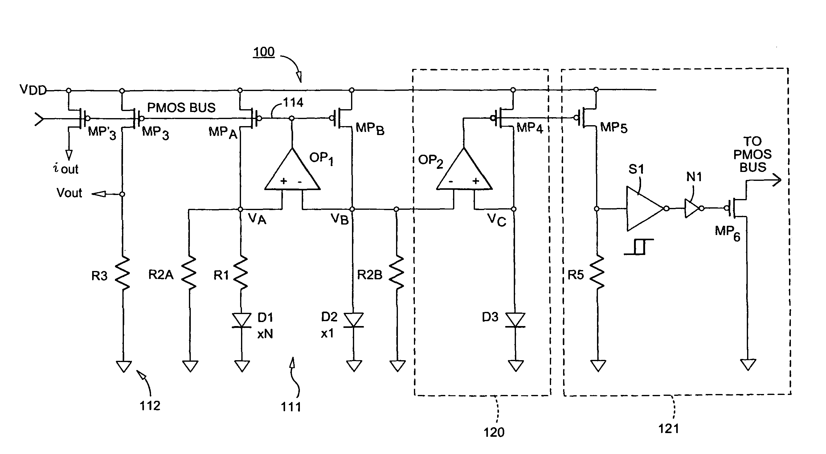
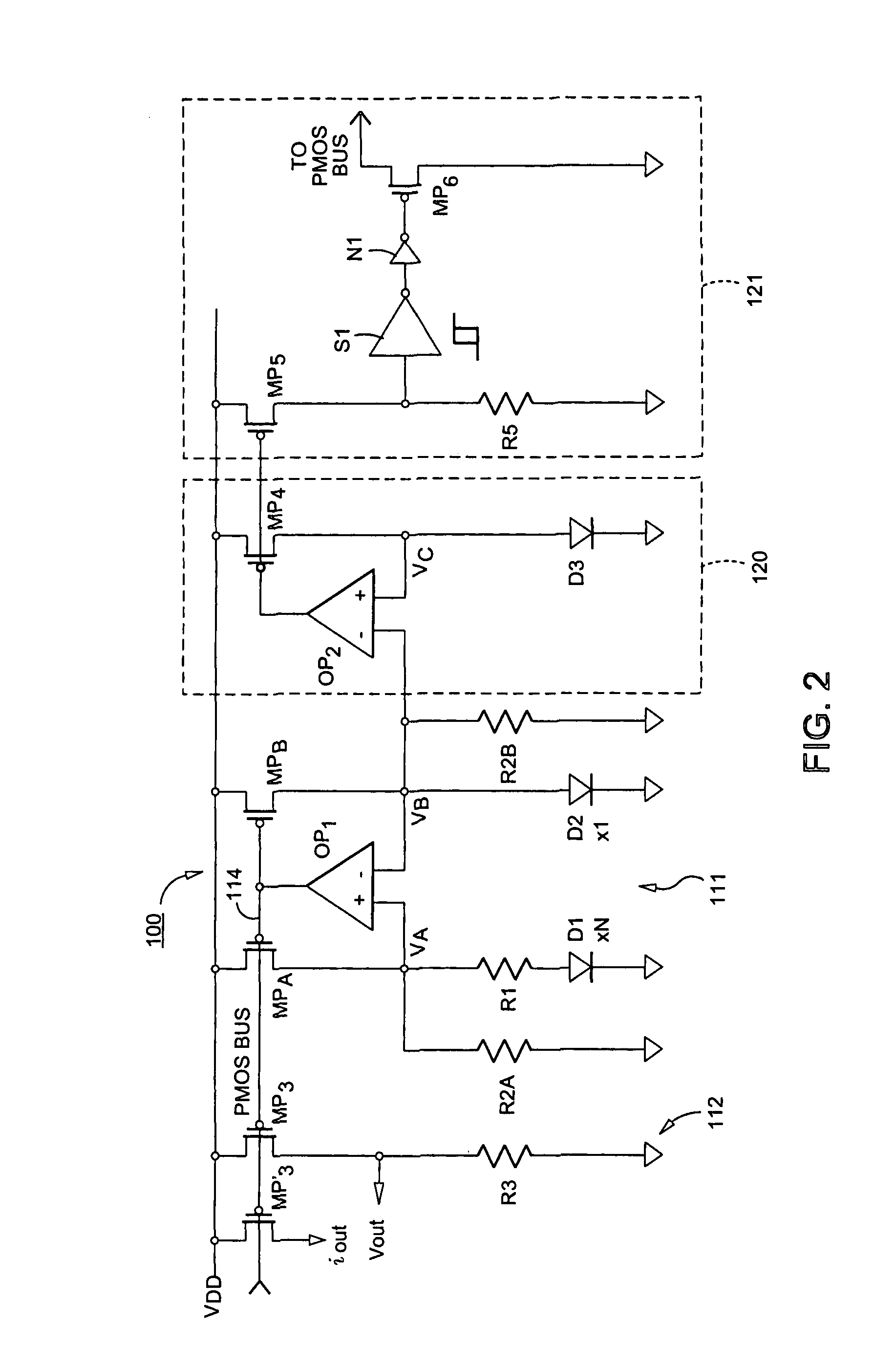
[0028]FIG. 2 is a detailed schematic according to a first embodiment of the invention. FIG. 2 shows bandgap reference circuit 100 which includes a bandgap core 111 and an output circuit 112. Bandgap core 111 and output circuit 112 are generally similar to corresponding elements shown in FIG. 1 herein, and descriptions thereof will therefore be omitted in the interest of brevity.

[0029]FIG. 2 also shows start-up circuitry which includes a sampling circuit 120 and a current injection circuit 121. The sampling circuit 120 operates to sample current in diode D2, and to mirror that current through emulation diode D3. Emulation diode D3 is identical to the sampled diode, here, diode D2. Sampling circuit 120 includes op-amp OP2 whose negative differential input is connected to diode D2 thereby sampling voltage VB. The positive input to op-amp OP2 is connected to emulation diode D3 which is series-connected to transistor MP4. Transistor MP4 forms a current source for current flowing through ...


PUM


Abstract

A start-up circuit for a bandgap reference circuit includes a sampling circuit for sampling current through a diode in one of first and second diode / resistor networks that respectively provide complementary PTAT and CTAT characteristics in the bandgap reference, and a current injection circuit to inject current to a PMOS bus of the bandgap reference if the sampled current is not higher than a pre-designated low value. By virtue of this operation, since current through the diode itself is sampled, the start-up circuit ensures that current through the sampled diode is higher than the pre-designated low value, thereby leading to rapid start-up of the bandgap reference to a stable operating point.

Description

FIELD OF THE INVENTION[0001]The present invention relates to a start-up circuit for a bandgap reference voltage circuit, such as a bandgap reference circuit that produces a voltage and / or a current reference, and particularly a bandgap reference circuit that provides a low-level voltage and / or current as its output.BACKGROUND OF THE INVENTION[0002]One important part of many analog and digital devices is a generator for a voltage reference or a current reference which exhibits good characteristics. Here, “good characteristics” means that the generator for the reference generates a voltage or a current that is stable or changes only nominally over a wide range of supply voltages (which typify battery-powered devices) and over a wide range of temperature variations, and which can also be implemented with existing fabrication processes, preferably as part of other circuitry for the device.[0003]The bandgap reference is a popular reference generator that successfully satisfies these requ...

Claims


Application Information

Patent Timeline
Patent Type & Authority Patents(United States)
IPC IPC(8): G05F1/10G05F3/02
CPCG05F3/30
Inventor SINITSKY, DENNIS
Owner MARVELL ASIA PTE LTD
Why Eureka
Try Eureka