Controller for clock skew determination and reduction based on a lead count over multiple clock cycles

a clock cycle and control board technology, applied in the field of integrated circuits, can solve the problems of complex logic core design, signal to travel faster or slower, etc., and achieve the effect of measuring or describing the amount of jitter in the clock signal

Active Publication Date: 2010-08-03
ADVANCED MICRO DEVICES INC
View PDF23 Cites 32 Cited by
  • Summary
  • Abstract
  • Description
  • Claims
  • Application Information

AI Technical Summary

Benefits of technology

[0010]Additionally, the same techniques for detecting and measuring clock skew may also be used to detect and measure jitter in the clock signals, according to some embodiments. For example, in a system with no clock skew or in a system for which clock skew has been compensated using variable delay adjusters, as described herein, the jitter may be expected to effect each clock signal equally. Thus, after correcting for skew, the jitter may be expected to cause a first clock signal to lead a second clock signal about as many times as the second clock signal leads the first clock signal. By configuring variable delay adjusters on the clock signals, the amount of jitter in the clock signals can be measured or characterized.

Problems solved by technology

Typically, complex logic core designs rely on one or more clocks for operational synchronization.
Clock skew refers to a phenomenon in which a clock signal arrives at different components at different times. The difference in arrival time may be caused by the clock signal traveling different distances to different components or may also be caused by defect or flow in materials or manufacturing causing the clock signal to travel faster or slower along a pathway than expected.
Buffer delays and wiring delays are the two most significant factors contributing to skew.
The clock topology can significantly contribute to skew.

Method used


Image

  • Controller for clock skew determination and reduction based on a lead count over multiple clock cycles
  • Controller for clock skew determination and reduction based on a lead count over multiple clock cycles
  • Controller for clock skew determination and reduction based on a lead count over multiple clock cycles

Examples


Embodiment Construction

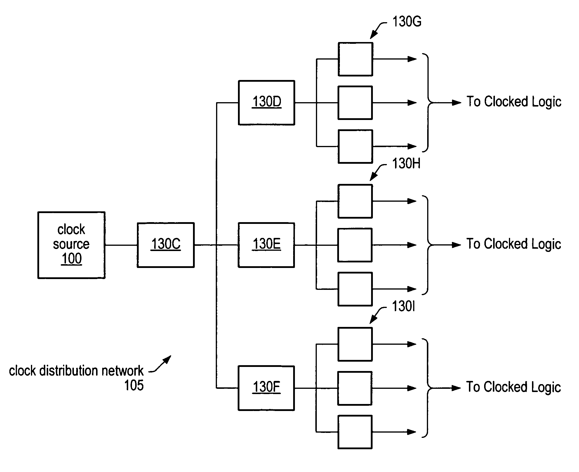
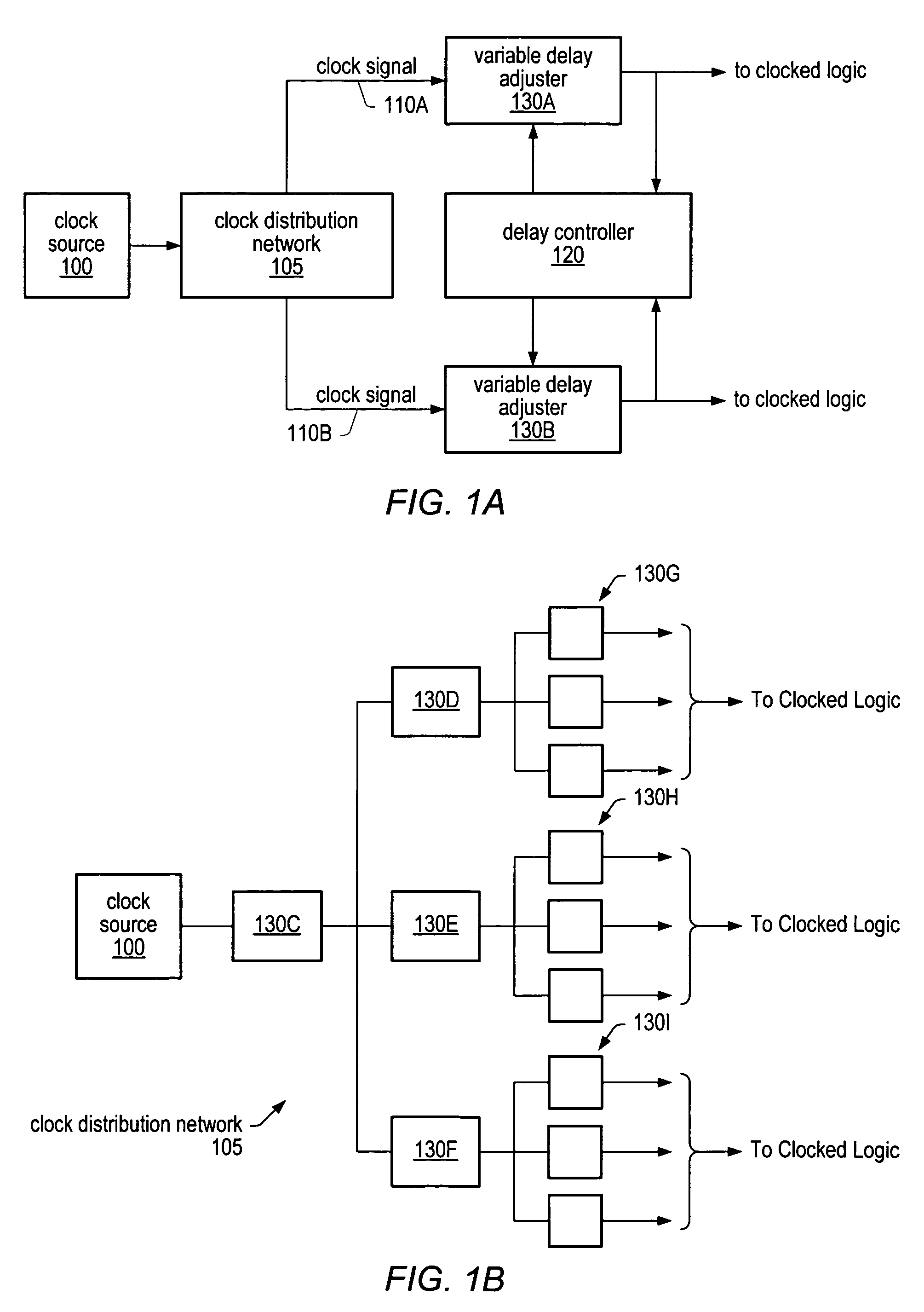
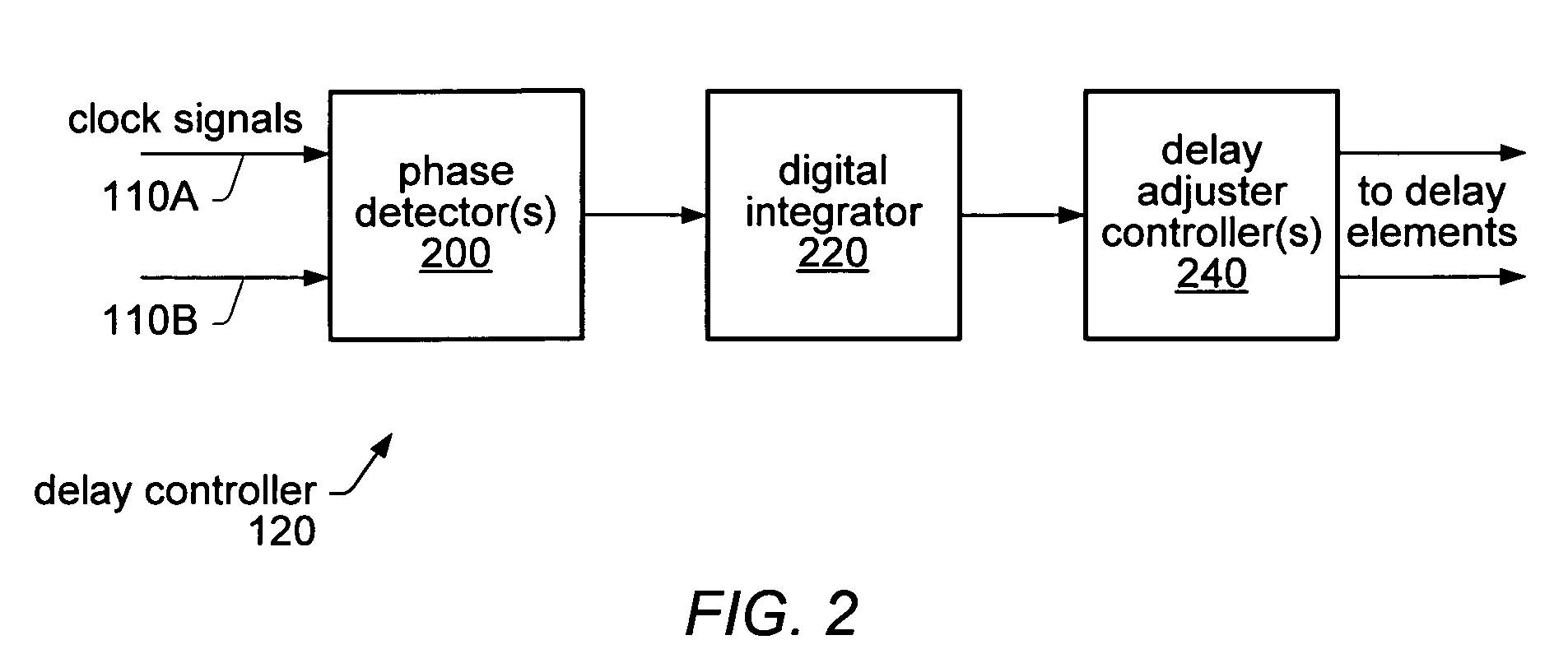
[0027]As noted above, clock skew, duty cycle and / or clock jitter may be detected, measured and, in some cases, corrected using phase detectors, digital counters and adjustable delay controllers. FIG. 1A is a block diagram illustrating one embodiment of circuit logic for determining and correcting clock skew in an integrated circuit. As illustrated in FIG. 1A, an integrated circuit may include a clock source 100 that is routed through a clock distribution network 105 to divide or split the clock signal into multiple signals, such as clock signals 110A and 110B. For example, clock distribution network 105 may represent a clock tree, grid, or other distribution network, according to various embodiments. While FIG. 1A only shows two resultant clock signals, namely 110A and 110B, FIG. 1A only illustrates a single, exemplary embodiment and other embodiments may include many more clock signals output from clock distribution network 105. As noted above, variable delay adjusters, such as var...


PUM


Abstract

Clock skew may be detected measured and compensated for using phase detectors and variable delay adjusters. Phase detectors may be distributed throughout a clock distribution network and may be configured to analyze two clock signals to determine how often one signal leads the other. The output of the phase detectors may be measured and counted over a large number of clock cycles. The difference between the number of times one signal leads or lags behind the other may be used to determine the amount of delay to apply to the leading clock signal in order to minimize (reduce) skew between the two clock signals. The same techniques for detecting and measuring clock skew may also be used to detect and measure jitter in the clock signals. By configuring variable delay adjusters on clock signals, the amount of jitter in the clock signals can be measured or characterized.

Description

BACKGROUND OF THE INVENTION[0001]1. Field of the Invention[0002]This invention is related to the field of integrated circuits, and more particularly, to methods and systems for measuring and adjusting various characteristic of clock signals, such as clock skew, duty cycle and jitter.[0003]2. Description of the Related Art[0004]Typically, complex logic core designs rely on one or more clocks for operational synchronization. Some of the desirable qualities for a clock signal may be an extremely small period, very short rise and / or fall times, low jitter, available everywhere on the chip with very low skew, and the ability to drive heavy loads at any point on the chip, while consuming the least possible amount of power.[0005]Clock skew may be defined as the difference in time between simultaneous clock transitions within a system. Skew has become the major part of constraints that form the upper boundary for the system clock frequency. Clock skew refers to a phenomenon in which a clock...

Claims


Application Information

Patent Timeline
Patent Type & Authority Patents(United States)
IPC IPC(8): G06F1/04
CPCG06F1/10
Inventor SEARLES, SHAWNJOHNSON, SCOTT C.WALTERS, DONALDRACHALA, RAVINDER
Owner ADVANCED MICRO DEVICES INC
Why Eureka
Try Eureka