
Ballistic systems having an impedance barrier

a technology of impedance barrier and ballistic system, which is applied in the direction of fluid removal, drilling machine and method, borehole/well accessories, etc., can solve the problem of reducing the production capacity of hydrocarbon bearing formations

Active Publication Date: 2010-08-10
BAKER HUGHES HLDG LLC
View PDF21 Cites 31 Cited by
  • Summary
  • Abstract
  • Description
  • Claims
  • Application Information

AI Technical Summary

Benefits of technology

The impedance barrier effectively isolates shaped charges from shock waves, maintaining the integrity and depth of perforations, thereby enhancing hydrocarbon production capabilities.

Problems solved by technology

Curved and shorter perforations present an undesired condition since this can reduce the production capability of hydrocarbon bearing formations.

Method used


Image

  • Ballistic systems having an impedance barrier
  • Ballistic systems having an impedance barrier
  • Ballistic systems having an impedance barrier

Examples


Embodiment Construction

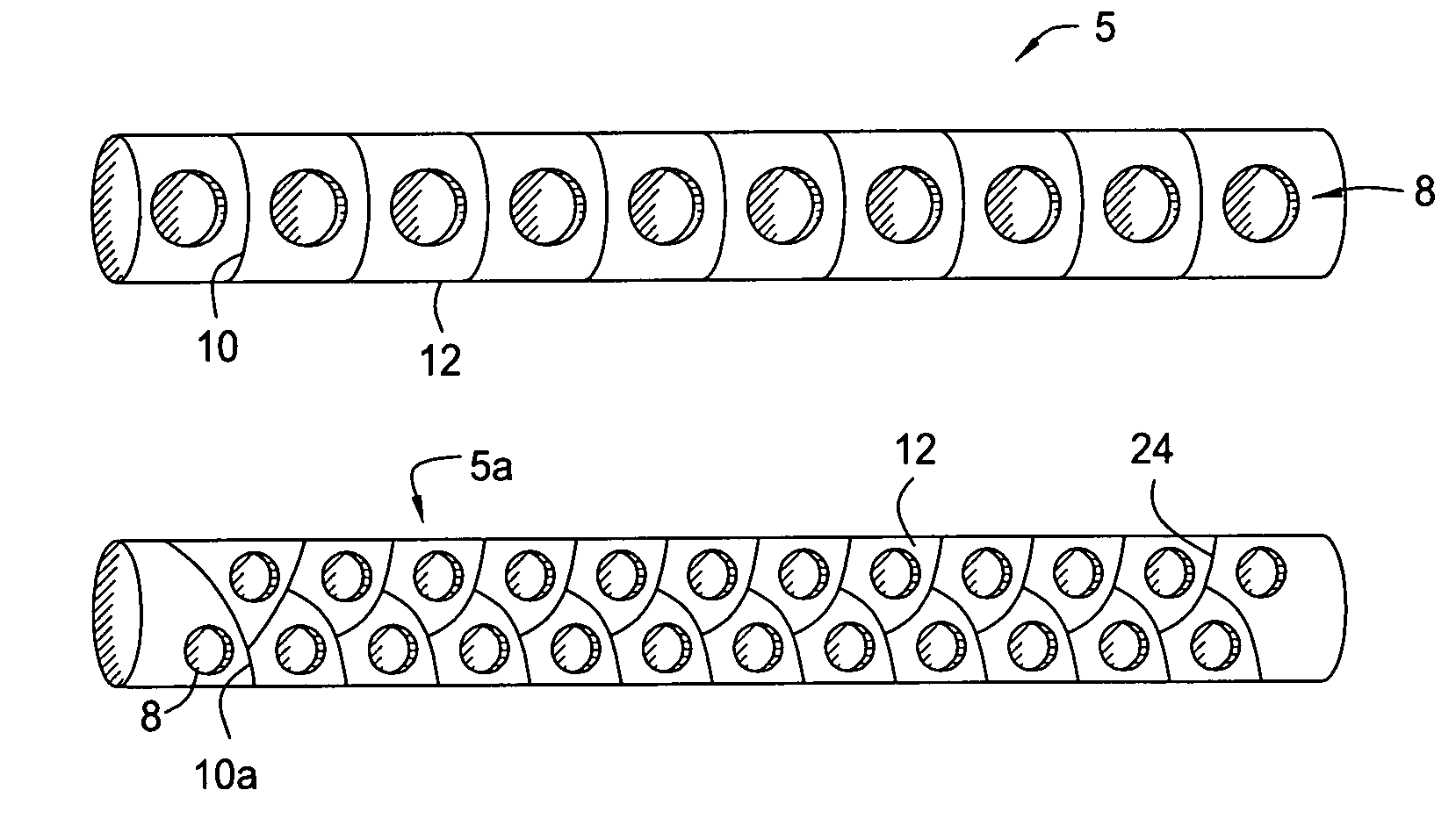
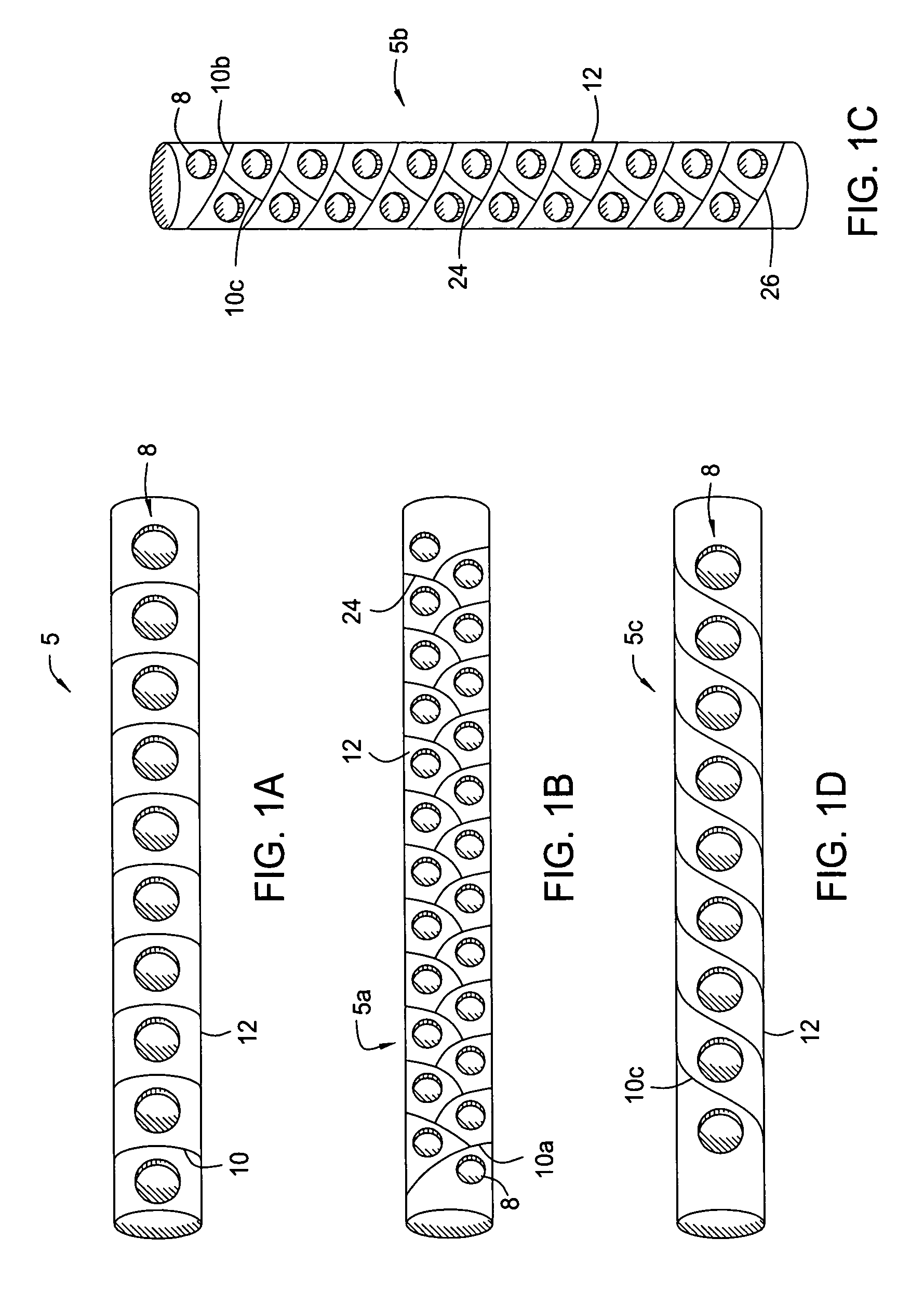
[0017]The present device disclosed herein addresses the problem of shock wave interference in ballistics systems by providing an impedance barrier between the shock producing sources. FIG. 1a demonstrates an embodiment of a shaped charge assembly having an impedance barrier as disclosed herein. The shaped charge assembly 5 of FIG. 1a comprises a shaped charge holder 12 with bores 8 formed thereon with an impedance barrier 10 positioned between the bores 8. The shaped charge holder 12 can be any device used to hold and retain shaped charges, such as a gun body, gun tube, or any other type of carrier used for carrying and holding shaped charges. The shaped charge holder 12 may alternatively be a unibody type, such as a single piece or single body. The bores 8 on the shaped charge holder 12 should be formed to receive and hold therein the perforating shaped charges. Accordingly, when fully assembled, the shaped charge assembly would further include shaped charges within the bores 8 and...


PUM


Abstract

A shaped charge assembly for use in a perforating gun that comprises a shaped charge holder, two or more shaped charges, slots formed to receive the shaped charges, and an impedance barrier disposed between adjacent shaped charges. The impedance barrier can comprise a gap formed in the shaped charge holder, where the impedance barrier runs across the shaped charge holder. The impedance barrier can be a void formed on the surface of the shaped charge holder, or can include shock attenuating material therein, such as wood, cork, cotton, polymeric materials, and combinations thereof, to name a few.

Description

RELATED APPLICATIONS[0001]This application claims priority from co-pending U.S. Provisional Application No. 60 / 730,671, filed Oct. 27, 2005, the full disclosure of which is hereby incorporated by reference herein.BACKGROUND OF THE INVENTION[0002]1. Field of the Invention[0003]The invention relates generally to the field of oil and gas production. More specifically, the present invention relates to a ballistic system including an impedance barrier. Yet more specifically, the present invention relates to a perforating gun system whose shaped charges are held in a medium, and where a gap is formed within the medium between each adjacent shaped charge.[0004]2. Description of Related Art[0005]Perforating systems are used for the purpose, among others, of making hydraulic communication passages, called perforations, in wellbores drilled through earth formations so that predetermined zones of the earth formations can be hydraulically connected to the wellbore. Perforations are needed becau...

Claims


Application Information

Patent Timeline
Patent Type & Authority Patents(United States)
IPC IPC(8): E21B7/00E21B43/116
CPCE21B43/117E21B43/1195
Inventor HARVEY, WILLIAMMAYSELESS, MEIRSCHWARTZ, ANNASAMPSON, TIMOTHYSLOAN, MARKMCCANN, JASONHETZ, AVIGDOR
Owner BAKER HUGHES HLDG LLC
Learn More