Assembly of buoys for flexible submarine pipe

a technology of flexible submarine pipes and buoys, which is applied in the installation of cables on floats, waterborne vessel navigational aids, special-purpose vessels, etc., can solve the problems of fragility of the surface layers of the submarine pipe, the submerged pipe is subject to considerable tensile forces, etc., and achieves more effective sustentation efforts, longer downtime, and more effective locking

Inactive Publication Date: 2010-08-10
TECH FRANCE SA
View PDF21 Cites 15 Cited by
  • Summary
  • Abstract
  • Description
  • Claims
  • Application Information

AI Technical Summary

Benefits of technology

[0010]A characterizing feature of the invention thus resides in the provision of a hitching line, to which the buoys or floaters are attached one after the other, which floaters are locked in the translational sense on this hitching line. Furthermore, the connecting devices permit the hitching line, to which the floaters are immovably attached, to be maintained in position along the desired section of pipe. In this way, all that is required for the displacement of the set of buoys or floaters along the submarine pipe is to pull the hitching line in the translational sense, and the line itself then pulls along all the buoys or floaters, without having to remove each of the buoys or floaters and displacing them one by one along the pipe. Furthermore, there is no need to provide a more rigid insert on the pipe in the vicinity of each floater, as the latter is now attached in a sliding manner on the pipe and does not compress it. The installation of the rigid inserts according to the prior art, in positions to be determined at the moment of installation of the pipe, required manual operations and a longer downtime for that means of implementation.
[0011]According to one particularly advantageous mode of implementation of the invention, each of the buoys or floaters exhibits a central transcurrent hole adapted to receive the submarine pipe in a freely sliding manner. Each buoy or floater thus completely surrounds the pipe, which permits more effective distribution of the sustentation efforts on the pipe. Further, the pipe is mounted in a sliding manner in each of the buoys or floaters, such that the act of pulling the hitching line along the pipe permits the buoys or floaters to be slid on the pipe in a single operation.
[0012]Furthermore, and advantageously, each of the buoys or floaters exhibits a peripheral transcurrent hole. The hitching line passes through the buoys or floaters making up the plurality via the peripheral transcurrent hole so as to ensure more effective locking in the translational sense of each buoy or floater on the hitching line and, in conjunction with the displacement of the buoys or floaters along the pipe, so as to exert longitudinal tensile forces as close as possible to the central transcurrent hole in order to obtain better guiding of the buoys or floaters as they slide on the pipe.
[0014]Each of the sleeves is divided advantageously into two separable semi-sleeves that are mutually symmetrical in relation to another axial plane. The semi-sleeves are equipped with threaded tightening elements for the purpose of holding the hitching line by force between the semi-sleeves. In this way, the position of the sleeves is adjustable and can be predetermined in order to adjust the distance between the buoys or floaters.

Problems solved by technology

In deep water, when the sea floor and the surface are very far apart, submarine pipes are subjected to considerable tensile forces which are limited in part by the presence of buoys or floaters.
One disadvantage associated with the fitting of these clamps around the submarine pipe lies in the fragility of the surface layers of the said pipe.
A further drawback associated with the above device is that the translational displacement of these floaters along the submarine pipe, for example in order to adjust the distribution of the tensile forces, and in the event that this may not have been sufficiently well evaluated, requires that submarine pipe be raised to the surface in order to readjust the positions of all the cylindrical sleeves.

Method used


Image

  • Assembly of buoys for flexible submarine pipe
  • Assembly of buoys for flexible submarine pipe

Examples


Embodiment Construction

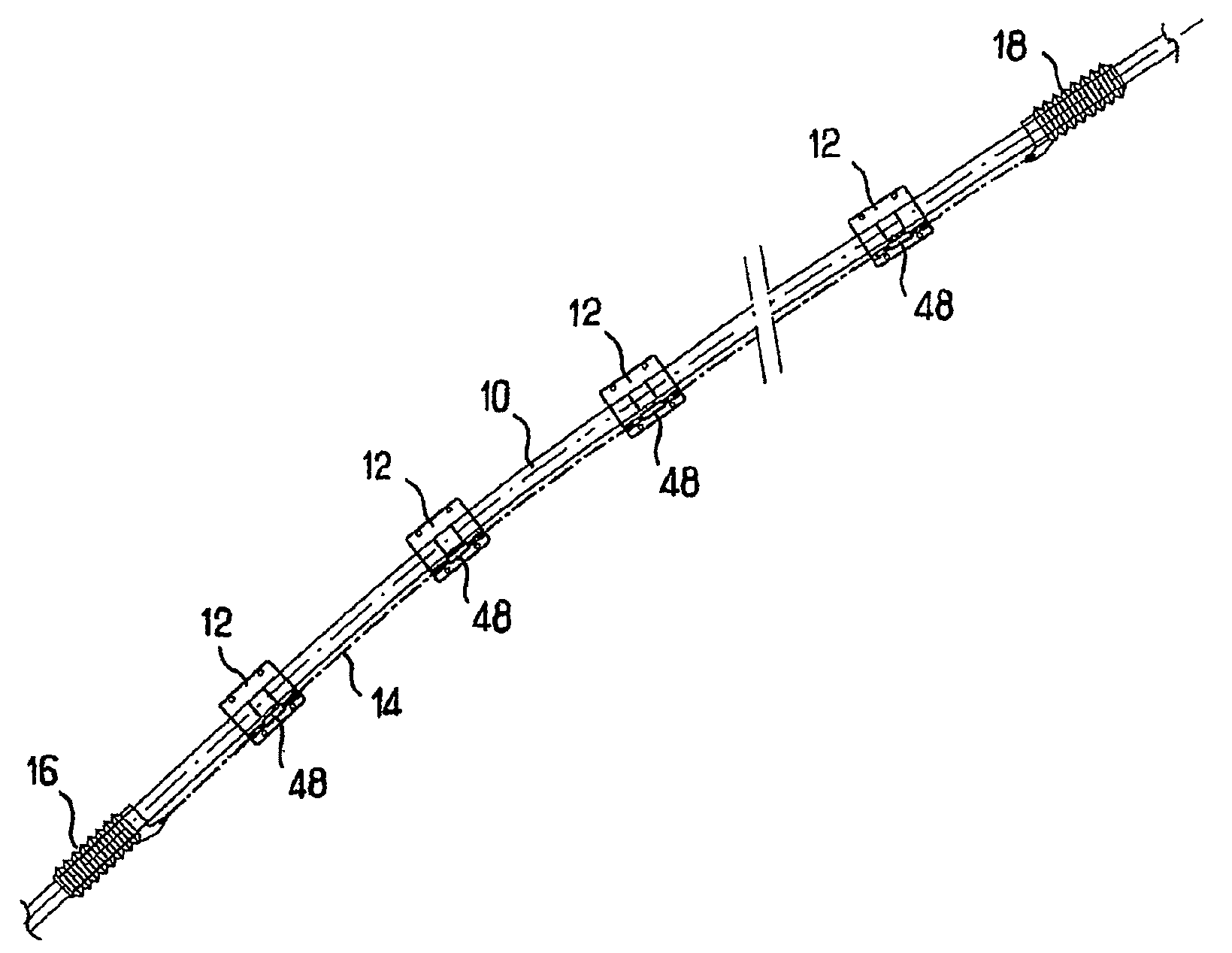
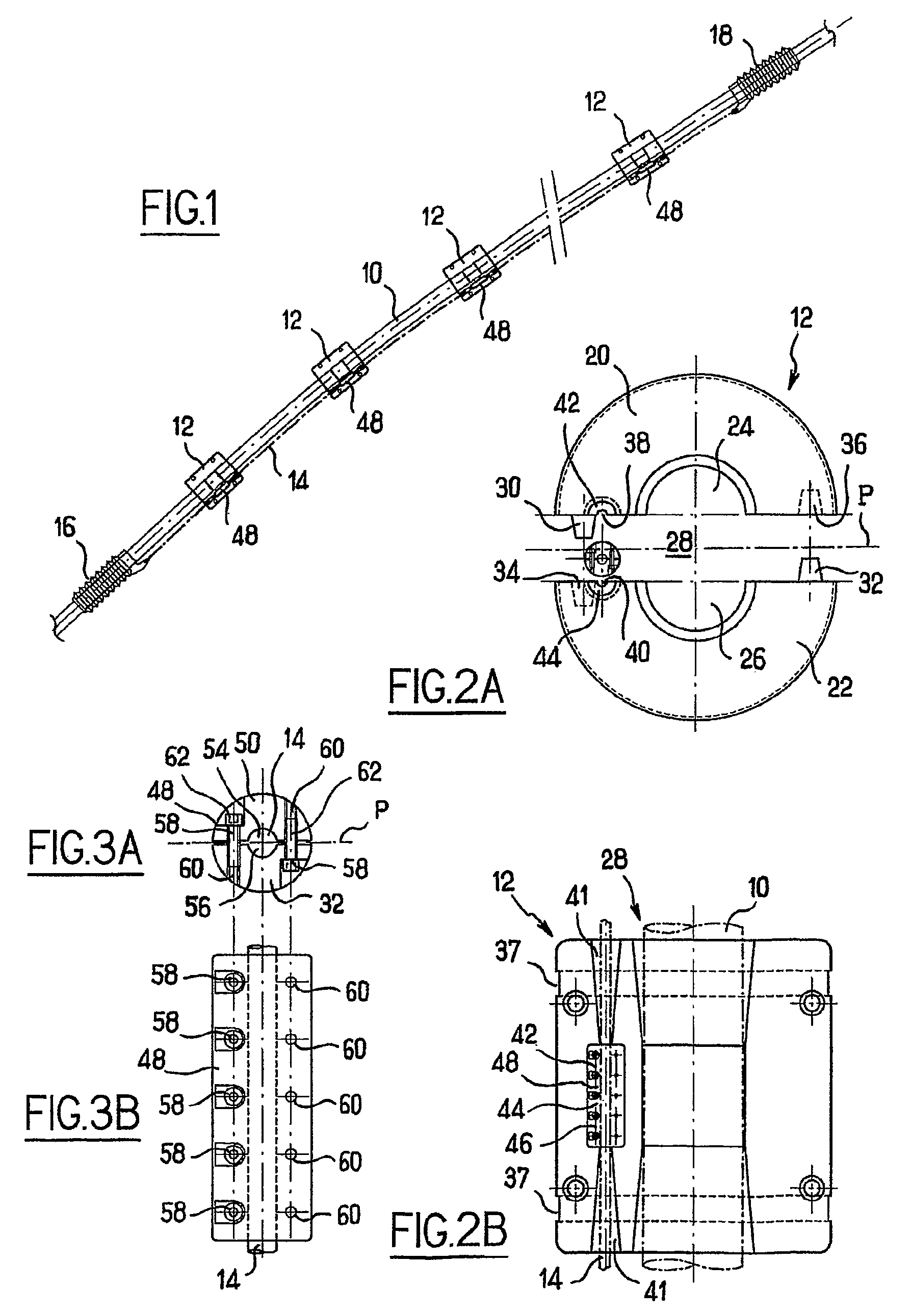
[0022]FIG. 1 depicts a section of flexible submarine pipe 10, intentionally truncated, which is adapted to extend between a sea floor installation and a surface installation that are not illustrated here. This section of submarine pipe 10 is equipped with a set of buoys or floaters 12. Four are shown in FIG. 1 in the interests of the clarity of the drawing, although they are considerably more numerous in reality. As explained in further detail below, each of the buoys or floaters 12 surrounds the pipe 10. The floaters are connected together successively by hitching line 14, for example in the form of a cable. This hitching line 14 is maintained extended along the pipe 10 due to the presence of two clamps 16, 18 locked in the translational sense on the pipe 10 to either side of the set of buoys or floaters 12.

[0023]Each buoy or floater 12 is connected in the translational sense to the hitching line 14, which itself is maintained in a fixed position along the pipe 10. The buoys or flo...


PUM


Abstract

An assembly of support buoys for a flexible submarine pipeline which is designed for the transport of hydrocarbons. A plurality of buoys which can be installed gradually on at least one portion of the flexible submarine pipeline. A fixing device blocks translational movement of the buoys on the portion of the pipeline. The fixing device includes a hitching or coupling line which connects each of the buoys successively to one another. The translational movement of each of the buoys is gradually blocked on the coupling line. Connecting devices maintain the coupling line taut at locations along the portion of the pipeline.

Description

CROSS-REFERENCE TO RELATED APPLICATIONS[0001]The present application is a 35 U.S.C. §§371 national phase conversion of PCT / FR2006 / 002586, filed Nov. 24, 2006, which claims priority of French Patent Application No. 05 / 12017, filed Nov. 28, 2005, the disclosure of which has been incorporated herein by reference. The PCT International Application was published in the French language.BACKGROUND OF THE INVENTION[0002]The present invention relates to a set of floaters or buoys for flexible submarine pipes.[0003]These submarine pipes are intended for the transport of hydrocarbons. The pipes are generally spaced out in the form of a catenary between a sea floor installation and a surface installation.[0004]In deep water, when the sea floor and the surface are very far apart, submarine pipes are subjected to considerable tensile forces which are limited in part by the presence of buoys or floaters. These buoys are generally installed one after the other on selected sections of the submarine ...

Claims


Application Information

Patent Timeline
Patent Type & Authority Patents(United States)
IPC IPC(8): B63B22/00B63B51/02
CPCE21B17/012H02G9/12F16L1/24
Inventor ROUTEAU, SYLVAINMILLET, JACQUES
Owner TECH FRANCE SA
Why Eureka
Try Eureka