Liquid crystal lens element and optical head device

a liquid crystal lens and optical head technology, applied in the field of liquid crystal lens elements, can solve the problems of slow response speed, complicated mechanical design of movable lenses, and increased size of optical head devices, and achieve the effects of low cost, excellent controllability, and small siz

Inactive Publication Date: 2010-08-10
ASAHI GLASS CO LTD
View PDF25 Cites 21 Cited by
  • Summary
  • Abstract
  • Description
  • Claims
  • Application Information

AI Technical Summary

Benefits of technology

[0051]According to the present invention, it becomes possible to realize a focal-length-continuous-variable liquid crystal lens which continuously changes transmission wavefront according to the magnitude of applied voltage.
[0052]Further, according to the present invention, by employing this liquid crystal lens in an optical head device, it is possible to correct an aberration generated the difference of cover thicknesses between optical disks. Further, since the number of input terminals into the element is as small as 3, it is possible to realize an optical head device excellent in controllability, small size and low cost.
[0053]Further, since in the first and second Fresnel lens portion provided in the liquid crystal lens element of the present invention, concave portions of the transparent material having a cross section of saw-tooth shape or a saw-tooth shape approximated by steps, are filled with a liquid crystal, although the element can is produce relatively large power component, the thickness of the liquid crystal layer can be reduced, which leads to low-voltage drive and high-speed response. Further, since extraordinary refractive index directions of the first and second liquid crystal layers are perpendicular to each other, stable spherical aberration correction can be realized without depending on direction of incident polarization. Further, according to the present invention, power component can be continuously changed by an electrode lens portion provided in the liquid crystal lens element.
[0054]Accordingly, in an optical head device provided with such a liquid crystal lens element, not only a spherical aberration generated due to the difference of cover thickness of a double layer optical disk but also a spherical aberration generated due to variation of cover thickness can be effectively corrected. Further, since deterioration of aberration is small even in a case where an objective lens is misaligned to the liquid crystal lens element at a time of tracking, an optical head device capable of stably carrying out writing and / or reading can be provided.BRIEF EXPLANATION OF THE DRAWINGS
[0055]FIG. 1: A side view showing the construction of a liquid crystal lens element of an embodiment according to the present invention.
[0056]FIGS. 2(A) and (B): FIG. 2(A) is a plan view showing a saw-tooth-shaped annular portions constituting a concave-convex portion of a first substrate of the liquid crystal lens element shown in FIG. 1, and FIG. 2(B) is a plan view showing annular electrode segments constituting a transparent electrode of a second substrate.

Problems solved by technology

However, in the means of (I) described in JP-A-2003-115127, when the movable lens group 160 is employed, a pair of lenses 161 and 162 and an actuator 163 are required, which causes problems that the size of the optical head device 100 increases and mechanical design for movable lens becomes complicated.
In particular, at a time of writing / reading a single layer or double layer DVD optical disk or a BD optical disk, a response of within 1 second is required for correction of wavefront aberration generated by a variation of cover thickness or switching of recording layers between single layer and double layer, and thus, slow response speed has been a problem.

Method used


Image

  • Liquid crystal lens element and optical head device
  • Liquid crystal lens element and optical head device
  • Liquid crystal lens element and optical head device

Examples


first embodiment

[0145]An embodiment of the present invention is described below with reference to attached drawings.

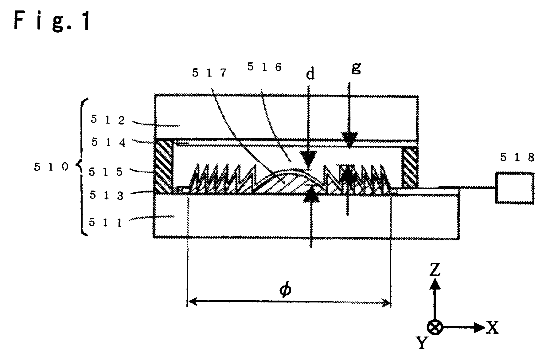
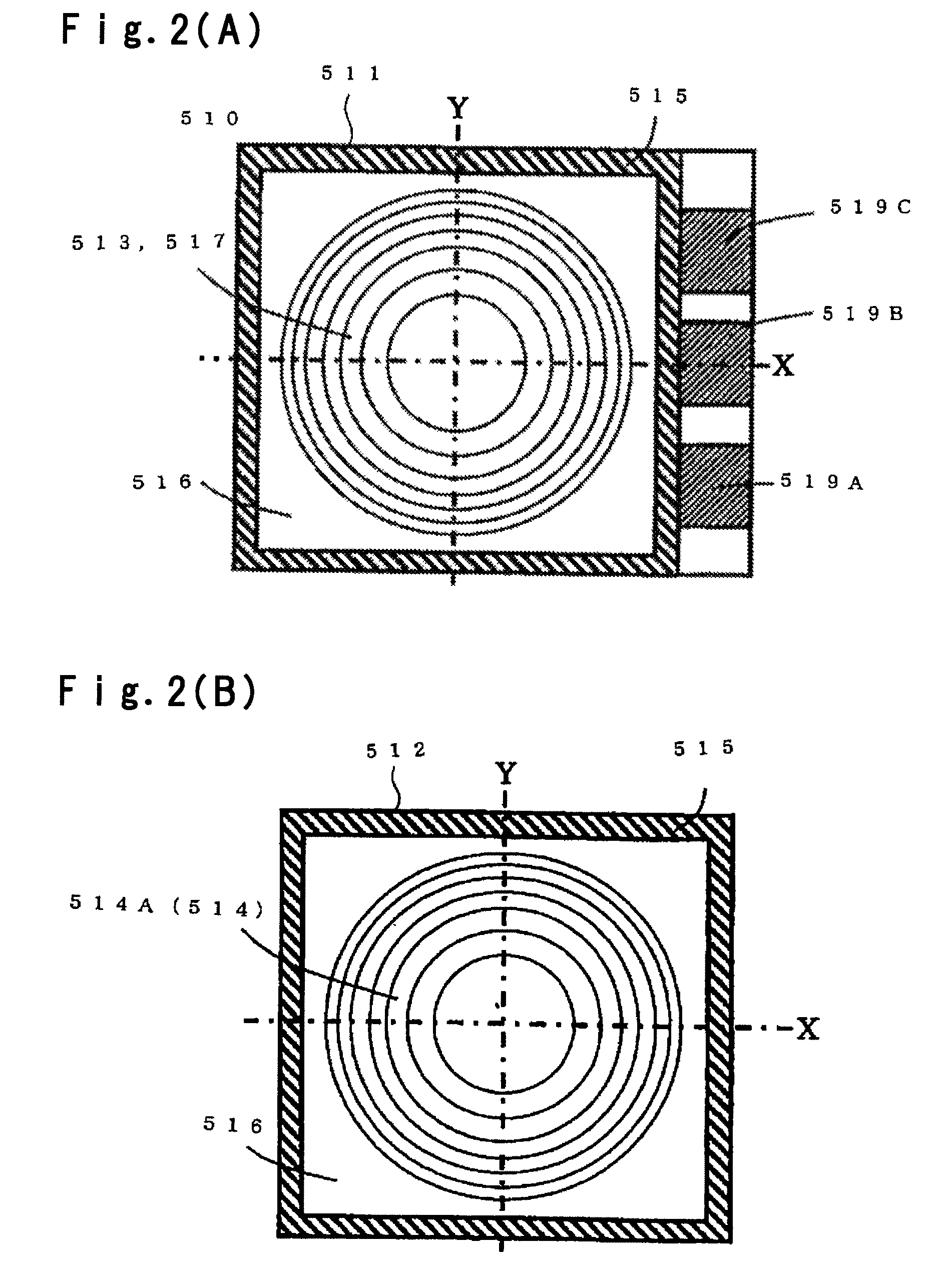
[0146]FIG. 1 shows a liquid crystal lens element 510 according to the first embodiment of the present invention and the liquid crystal lens element 510 comprises transparent substrates 511 and 512 (hereinafter referred to as first and second substrates 511 and 512), transparent electrodes 513 and 514, a seal 515, a liquid crystal layer (liquid crystal) 516, a concave-convex portion 517 and a driving power source circuit 518.

[0147]For the liquid crystal layer 516, a nematic liquid crystal having an ordinary refractive index no and an extraordinary refractive index ne (here, no≠ne) is employed. The concave-convex portion 517 is made of a transparent material of refractive index ns, and has a concave-convex-shaped cross section having a depth of d. The concave-convex portion 517 preferably has a saw-tooth-shape or a saw-tooth-shape approximated by steps, which has rotational symmetry abo...

second embodiment

[0214]An example of the construction of a liquid crystal lens element according to the second embodiment of the present invention is described below.

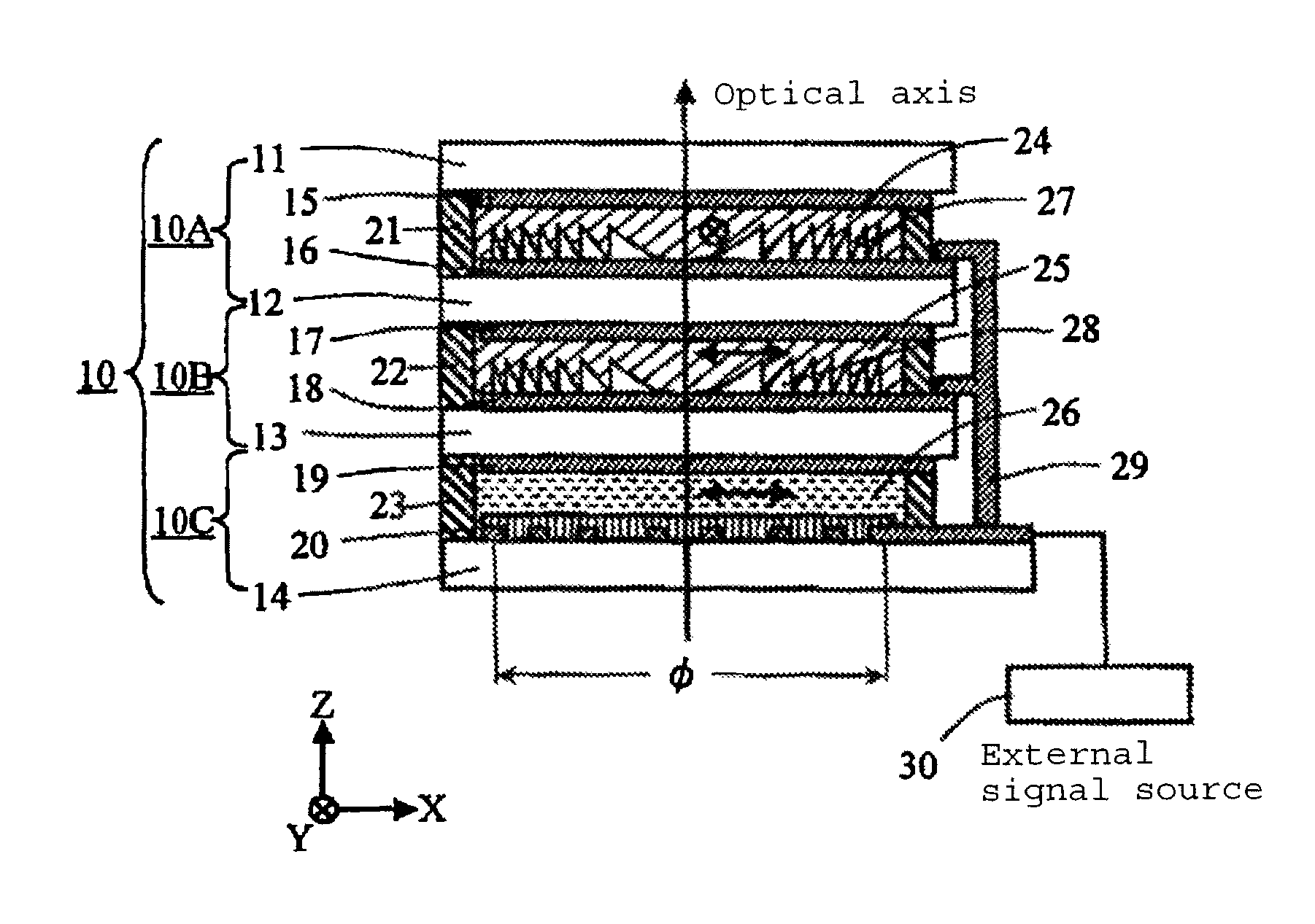
[0215]FIG. 14 is a cross sectional view showing the second embodiment of the liquid crystal lens element of the present invention. A liquid crystal lens element 10 according to this embodiment comprises, as its general construction, a first Fresnel lens portion 10A, a second Fresnel lens portion 10B and an electrode lens portion 10C, and they are integrally formed by laminating four transparent substrates 11 to 14 and three liquid crystal layers 24 to 26.

[0216]In the following embodiments, a liquid crystal lens element includes at least one Fresnel lens portion and at least one electrode lens portion, and a Fresnel lens portion corresponds to entire construction of the liquid crystal lens element of the first embodiment. Accordingly, the construction of each of the following embodiments can be constituted by adding an electrode lens por...

third embodiment

[0270]Then, a liquid crystal lens element according to the third embodiment of the present invention is described with reference to FIG. 21.

[0271]FIG. 21 is a top view of a complex electrode provided in the third embodiment of the liquid crystal lens element of the present invention. The liquid crystal lens element of this embodiment has a construction, in the liquid crystal lens element 10 according to the second embodiment shown in FIG. 14, a transparent electrode 19 and a complex electrode 20 provided in the electrode lens portion 10C are replaced by complex electrodes 40 and 50 shown in FIG. 21. Accordingly, in this embodiment, since portions other than the electrode lens portion 10C are the same as those of the second embodiment, explanation to these portions are omitted and only the electrode lens portion 10C is described.

[0272]Complex electrodes 40 and 50 provided in the electrode lens portion 10C of this embodiment, are a pair of complex electrodes for applying a voltage to ...


PUM


Abstract

A liquid crystal lens element capable of finely adjusting focal length according to the magnitude of applied voltage, and an optical head device employing such a liquid crystal lens element, are provided.On one surface of a transparent substrate 511, a transparent electrode 513 and a concave-convex portion 517 made of a transparent material having a cross section shape approximated by a saw-tooth shape, are formed so as to constitute a plurality of annular portions, and on one surface of a transparent substrate 512, a transparent electrode 514 is formed. The transparent electrodes 513 and 514 constitute annular divided electrode segments, and division positions of the annular electrode segments are made to be agree with division positions of annular portions of the saw-tooth-shaped concave-convex portion 517 of the transparent substrate 511.

Description

TECHNICAL FIELD[0001]The present invention relates to a liquid crystal lens element, in particular, to a liquid crystal lens element which can switch focal length according to switching or magnitude of applied voltage, and to an optical head device employing the liquid crystal lens element and to be used for writing and / or reading an information to / from an optical recording medium.BACKGROUND ART[0002]As a recording media for reading an information by an optical method, various types of optical recording media (hereinafter referred to as “optical disks”) have been developed, each of which has an information recording layer formed on a light-incident side plane and a cover layer made of a transparent resin for covering the information recording layer. As these optical disks, e.g. CD optical disks or DVD optical disks have been known. Meanwhile, optical head devices for writing and / or reading (hereinafter referred to as “writing / reading”) an information to / from such DVD optical disks, ...

Claims


Application Information

Patent Timeline
Patent Type & Authority Patents(United States)
IPC IPC(8): G11B7/00G11B7/135
CPCG02F1/29G11B7/1353G11B7/1369G11B7/1374G11B7/1378G11B7/13925G02F1/133526G02F2001/294G11B2007/0006G11B2007/0013G11B2007/13722G11B2007/13727G02F1/294G02F1/13G02B5/18
Inventor MURATA, KOUICHINOMURA, TAKUJIOOSAWA, MITSUOOOI, YOSHIHARUTANABE, YUZURU
Owner ASAHI GLASS CO LTD
Why Eureka
Try Eureka