Hearing device with ear canal microphone

a technology of ear canal microphone and hearing device, which is applied in the field of hearing device, can solve the problem of occupying a small space for a microphone, and achieve the effect of compact design of the hearing devi

Inactive Publication Date: 2010-08-10
SIEMENS AUDIOLOGISCHE TECHN
View PDF9 Cites 7 Cited by
  • Summary
  • Abstract
  • Description
  • Claims
  • Application Information

AI Technical Summary

Benefits of technology

[0009]The cerumen protection system can be adapted to the presence of a microphone and if necessary designed correspondingly larger. In particular the cerumen protection system can be funnel-shaped. The funnel shape is particularly suitable for the sound passageway from the loudspeaker to the surface of the plastic mold, but however ensures an expansion of the cerumen protection system in which the microphone can be positioned, in the vicinity of the surface of the plastic mold. The funnel shape preferably comprises a conical segment which passes into a tube-like segment extending to the surface of the plastic mold. The microphone can be particularly easily accommodated in the tube-like segment. In this case, the microphone can either be arranged such that it is arranged with its membrane parallel to the sound exit orifice. Here the microphone can particularly effectively record the sound in the ear canal. Alternatively, the microphone with its microphone membrane can be arranged perpendicular to the sound exit opening. With this embodiment, a particularly space-saving arrangement is ensured particularly with the funnel shape of the cerumen protection system.

Problems solved by technology

Naturally however, there is only minimal space for a microphone in the plastic mold which can be inserted into the ear.

Method used


Image

  • Hearing device with ear canal microphone
  • Hearing device with ear canal microphone

Examples


Embodiment Construction

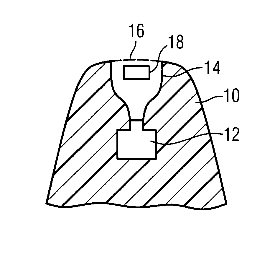
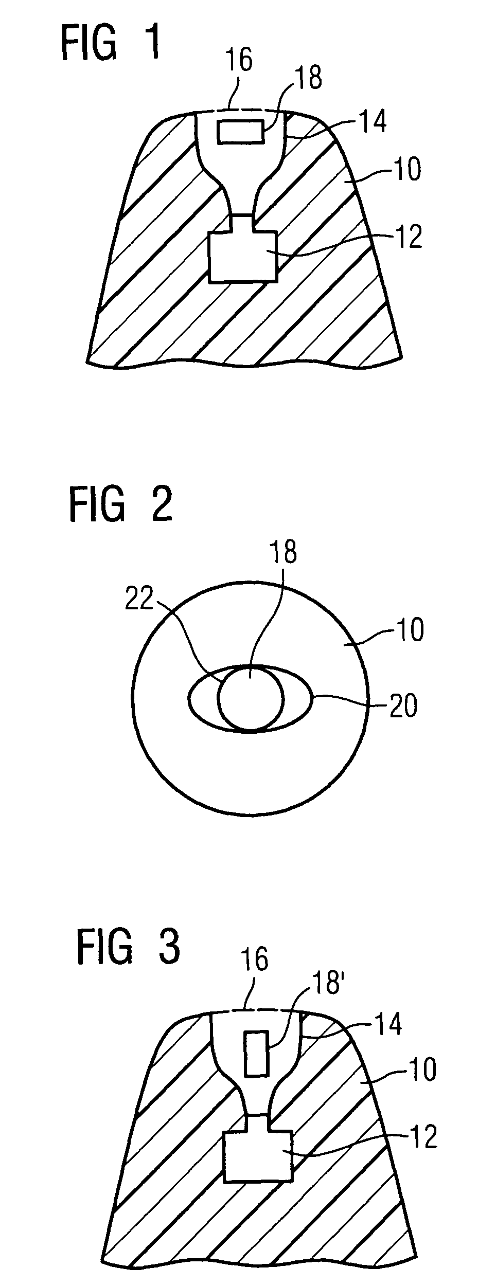
[0015]The present invention relates to a hearing device according to the claims. The hearing device features a plastic mold which can be arranged in the ear. This plastic mold can be the hearing device shell of an in-the-ear hearing device or an otoplastic which can be inserted into the ear, said otoplastic pertaining to a behind-the-ear device.

[0016]The interior of the hearing device features a loudspeaker.

[0017]A cerumen protection system extends from the loudspeaker to the surface of the plastic mold. A cerumen protection system serves to protect the loudspeaker from the penetration of the cerumen. It creates a path for the sound from the loudspeaker to the plastic mold without cerumen being able to reach the loudspeaker.

[0018]With an in-the-ear hearing device according to the invention, the hearing device is accommodated in a plastic mold, in a so-called hearing device shell. The plastic mold features a tip, which is inserted into the ear canal. Such a tip 10 of an in-the-ear he...


PUM


Abstract

A hearing device with a plastic mold arranged in the ear, in other words a hearing device shell or an otoplastic, features a loudspeaker in its interior. A cerumen protection system extends from the loudspeaker to the surface of the plastic mold. In accordance with the invention, a microphone is arranged in the cerumen protection system.

Description

CROSS REFERENCE TO RELATED APPLICATIONS[0001]This application claims priority of German application No. 102005019148.7 filed Apr. 25, 2005, which is incorporated by reference herein in its entirety.FIELD OF THE INVENTION[0002]The invention relates to a hearing device, particularly to a hearing device with ear canal microphone.BACKGROUND OF THE INVENTION[0003]A hearing device which can be worn in the ear and features a loudspeaker and a cerumen protection system is known from U.S. Pat. No. 6,164,409.[0004]A hearing device is further known from DE 41 28 172 C2, in which a second acoustic sensor is provided. This is inserted into the inner ear of the hearing device wearer, together with an electroacoustic converter (receiver).[0005]With future hearing devices, a series of additional functions is conceivable for use by hearing impaired, in which one prerequisite is that the acoustic signal in the ear canal is recorded. Naturally however, there is only minimal space for a microphone in t...

Claims


Application Information

Patent Timeline
Patent Type & Authority Patents(United States)
IPC IPC(8): H04R25/00A61N1/00
CPCH04R25/654
Inventor NIEDERDRANK, TORSTEN
Owner SIEMENS AUDIOLOGISCHE TECHN
Why Eureka
Try Eureka