Vehicular lamp

a technology for lamps and vehicles, applied in the field of lamps for vehicles, can solve the problems of not meeting the requirements of the light distribution regulations, front and rear of vehicles, and difficulty in making the light guide emit light equally

Inactive Publication Date: 2010-08-17
KOITO MFG CO LTD
View PDF12 Cites 43 Cited by
  • Summary
  • Abstract
  • Description
  • Claims
  • Application Information

AI Technical Summary

Benefits of technology

[0008]Therefore, embodiments of the present invention provide a vehicular lamp that can equalize the light emitted from a light guide and also control the directivity of this emitted light.
[0010]According to the vehicular lamp with the structure described above, the central axis that passes through the apex angle of every stippling step is slanted toward the predetermined emission direction of the light with respect to the virtual vertical line perpendicular to the reflective back surface. Therefore, the light emitted from the light source is incident from the side end surface of the light guide and is reflected by a plurality of stippling steps. After that, such light is given directivity from the light-emitting surface of the light guide and is emitted toward the predetermined direction. Thus, even if the light guide has large curvature, the light distribution regulations that require directivity toward the front or rear of the vehicle can be satisfied. In addition, the light guide is equally emitted within the range to satisfy the light distribution regulations and the directivity of light can also be controlled.
[0012]According to the structure described above, the introduction width of the light is equal to the thickness dimension of the light guide minus the height dimension of the stippling steps and is set to 90% or more of the thickness dimension of the light guide. Accordingly, the light that is emitted from the light source can be introduced efficiently.
[0014]According to a vehicular lamp with the structure described above, the light guide has a tapered shape such that the distance between the light-emitting surface and the reflective back surface gradually becomes more narrow from the side end surface on the light source side toward the other end surface. Thus, even if the light guide has large curvature, the distance from the stippling steps to the light-emitting surface becomes smaller. Consequently, the reflection angle of the introduced light is adjusted. As a result, the light from the light-emitting surface can be emitted unfailingly in the predetermined direction.
[0016]According to a vehicular lamp with the structure described above, the placement density of the stippling steps increases in proportion to the distance from the side end surface. Therefore, even if the light guide has large curvature, the amount of light reflected by the stippling steps is adjusted even at the end side that is far from the side end surface. Accordingly, the brightness of the light can be maintained at a level that is equal to that at the side end surface.
[0017]According to the vehicular lamp embodiments of the present invention, the light emitted from the light guide can be equalized and the directivity of the emitted light can also be controlled.

Problems solved by technology

As a result, it is difficult to make the light guide emit light equally.
In addition, it may not meet the requirements of the light distribution regulations for directivity to the front and rear of the vehicle.

Method used


Image

  • Vehicular lamp
  • Vehicular lamp
  • Vehicular lamp

Examples


Embodiment Construction

[0023]Embodiments of the present invention will be described below with reference to the drawings.

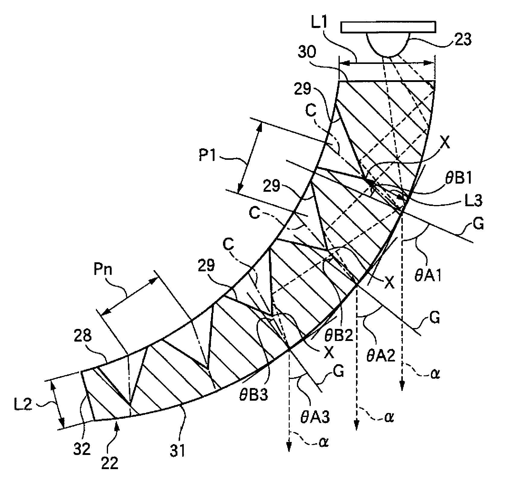
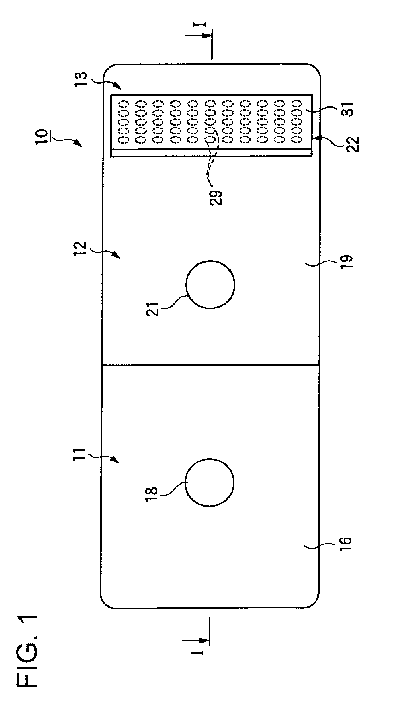
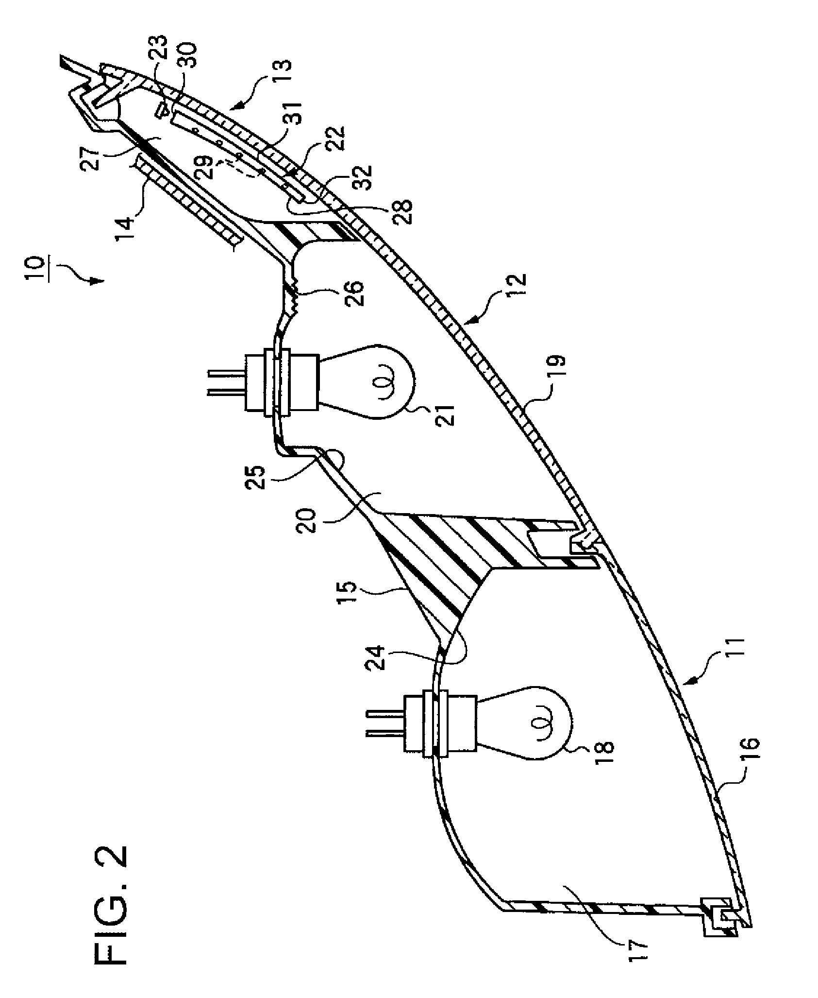
[0024]FIGS. 1 to 4 show an embodiment of a vehicular lamp according to the present invention. FIG. 1 is a frontal view of the vehicular lamp according to an embodiment of the present invention. FIG. 2 is a cross-sectional view along the I-I line in FIG. 1. FIG. 3 is a perspective view of the exterior appearance of a broken-out portion of a light guide applied to the vehicular lamp in FIG. 1 as seen from the internal surface side. FIG. 4 is a horizontal cross-sectional view explaining the light paths within the light guide shown in FIG. 3. Note that, the front, rear, left, and right directions in this explanation are based on the direction of the vehicle. In FIG. 2 the bottom side is the rear of the vehicle.

[0025]As shown in FIG. 1, a vehicular lamp 10, which is an embodiment of the present invention, is a rear combination lamp that includes, a stop lamp unit 11, a turning signal unit 12...


PUM


Abstract

A vehicular lamp includes a light source positioned inside a lamp chamber. The lamp chamber is formed from a lamp body fixed to a vehicle body and a front cover that covers a front open portion thereof. The vehicular lamp includes a light guide that includes a side end surface to which light emitted from the light source is incident on one side thereof; a light-emitting surface that emits the light that is incident from the side end surface in a predetermined direction; and a reflective back surface that has a reflecting portion that faces the light-emitting surface. The light guide made from translucent material that is positioned on one side inside the light chamber following along with the shape of the lamp front cover. A plurality of stippling steps that have a generally conical shape are provided on the reflective back surface of the light guide. A central axis that passes through an apex angle of every stippling step slants toward the predetermined emission direction of the light with respect to a virtual vertical line perpendicular to the reflective back surface.

Description

BACKGROUND OF INVENTION[0001]1. Field of the Invention[0002]The present invention relates to a vehicular lamp that includes a light guide, which is made from a translucent material and emits, in a predetermined direction, light that is emitted from a light source and is incident to the light guide.[0003]2. Related Art[0004]As an example of a conventional vehicular lamp, a vehicular lamp that includes a light guide with one end surface that faces a light source and that has a light incident surface is known (see Patent Document 1 for example).[0005]In the vehicular lamp disclosed in Patent Document 1, the light emitted by a turn signal lamp is incident to the light guide from the light incident surface and is lead to a terminal side of the side space. The light strikes the stippling steps and is reflected. Then, the reflected light is emitted outside from the surface of the light guide. Thus, the side surface illumination portion of the front cover is radiated to equalize the illumin...

Claims


Application Information

Patent Timeline
Patent Type & Authority Patents(United States)
IPC IPC(8): F21V9/00F21V1/00
CPCF21S48/2243F21S48/2268F21S48/2281G02B6/0036G02B6/0046F21S43/239F21S43/245F21S43/249
Inventor HIRANO, JUNICHINATSUME, KAZUNORI
Owner KOITO MFG CO LTD
Why Eureka
Try Eureka