Method of calibration for computed tomography scanners utilized in quality control applications

a computed tomography and quality control technology, applied in material analysis using wave/particle radiation, instruments, nuclear engineering, etc., can solve the problems of inadequate calibration methods and close calibration of equipmen

Active Publication Date: 2010-08-17
RTX CORP
View PDF10 Cites 14 Cited by
  • Summary
  • Abstract
  • Description
  • Claims
  • Application Information

AI Technical Summary

Problems solved by technology

However, such applications require close calibration of the equipment for performing the scanning.
To date, adequate calibration methods have not been developed.

Method used


Image

  • Method of calibration for computed tomography scanners utilized in quality control applications
  • Method of calibration for computed tomography scanners utilized in quality control applications
  • Method of calibration for computed tomography scanners utilized in quality control applications

Examples


Embodiment Construction

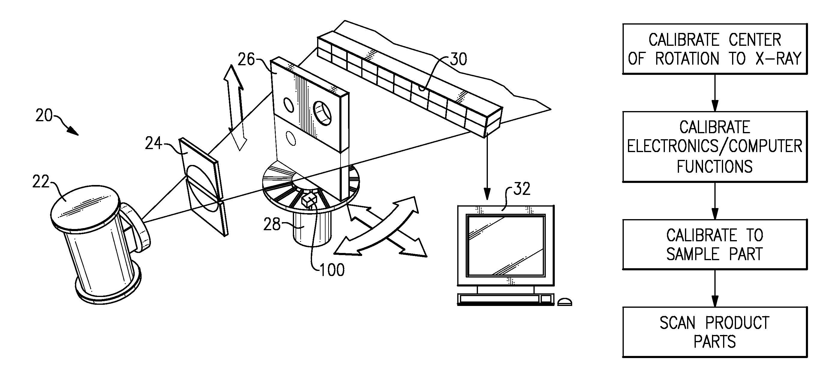
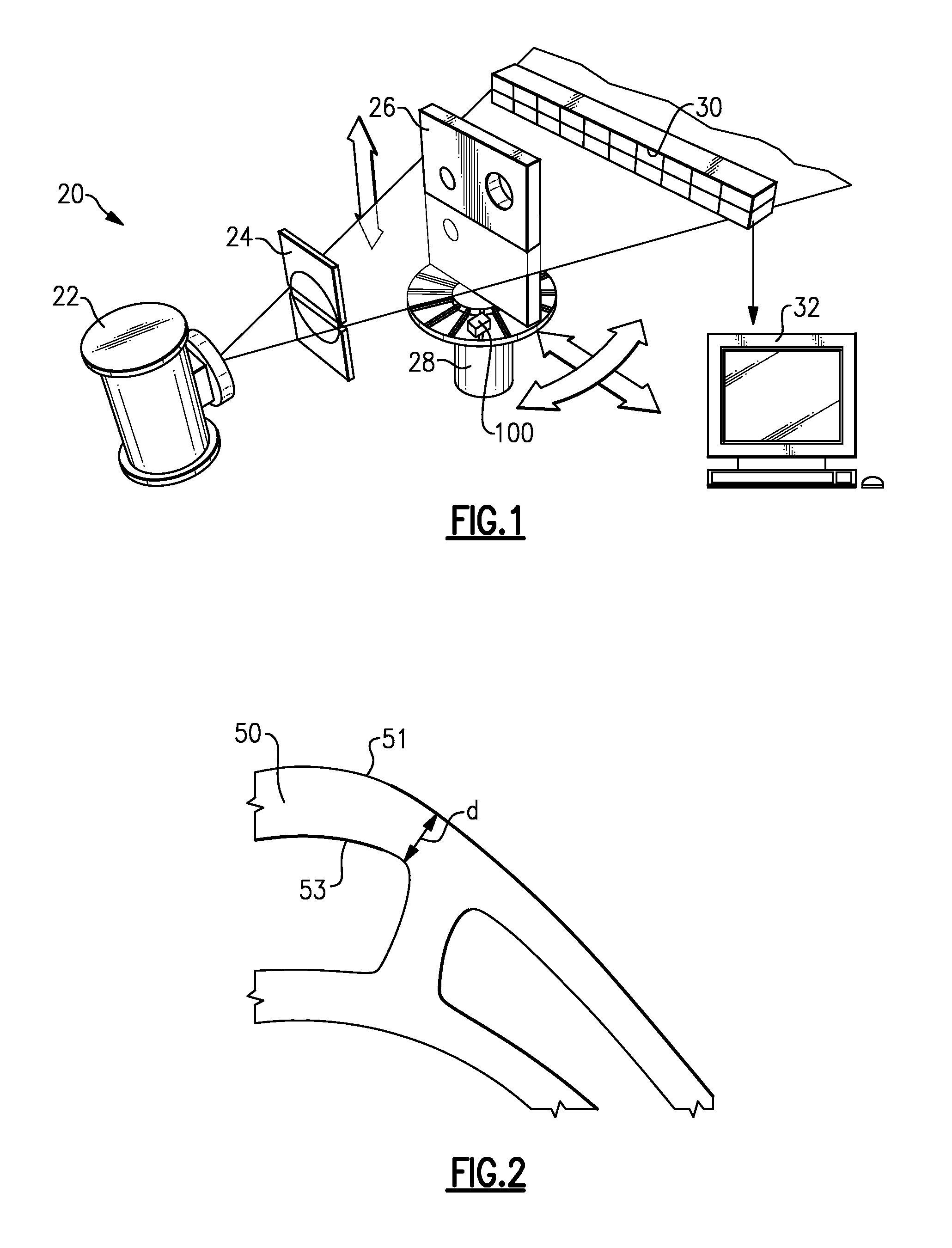
[0011]A system 20 for providing computed tomography inspections of a component 26 is illustrated in FIG. 1. As shown, an x-ray source, which may be a 450 KeV x-ray source, directs x-rays through a source collimation element 24, and through the component 26. An object positioning unit 28 rotates the component 360 degrees. A highly collimated discrete detector array 30 samples the x-ray absorption by the component 26. A computer 32 is provided with appropriate image analysis software, and can reconstruct an image with an accurately known geometric scale from the x-ray absorption data and positional information. Scaled images may be utilized to measure wall thicknesses by defining the pixels that are at a threshold that is half air and half material. The use of the system to provide such tolerance measurements is known.

[0012]One application which shows promise is checking the thicknesses of walls such as in a turbine blade 50 for a gas turbine engine. As shown in FIG. 2, a wall thickne...


PUM

PropertyMeasurementUnit
diameteraaaaaaaaaa
diameteraaaaaaaaaa
computed tomographyaaaaaaaaaa

Abstract

A method of calibrating a computed tomography system includes the steps of mounting a scan geometry defining tool on a rotating object positioning unit of a computer tomography scanner. The scan geometry defining tool has structure of precisely measured dimensions. A beam is directed from an x-ray source of the computed tomography system through the structure of the scan geometry defining tool. A detected image after absorption of the x-ray from the scan geometry defining tool is analyzed, and utilized to determine a distance from the x-ray source spot location to the center of rotation of the object positioning unit. A beam is also directed from the x-ray source through a system performance test standard tool and analyzes a number of electronic and computer performance characteristics. The analyzed characteristics can be compared to expected characteristics to provide feedback on the operation of electronic and computer functions within the computed tomography system.

Description

BACKGROUND OF THE INVENTION[0001]This application relates to a method of calibrating a computed tomography scanner that will be utilized in checking the tolerance ranges on manufactured components.[0002]Computed tomography scanners are utilized in a number of applications. Essentially, x-rays are passed through a part, and onto a highly collimated detector array. A signal from the array is then provided to an image analysis computer from the detector array.[0003]Computed tomography scanners have been widely utilized in various medical applications. More recently it has been proposed to utilize such scanners in quality control applications such as checking tolerances of manufactured components. However, such applications require close calibration of the equipment for performing the scanning. To date, adequate calibration methods have not been developed.SUMMARY OF THE INVENTION[0004]A method of calibrating a computed tomography system includes the steps of mounting a scan geometry def...

Claims


Application Information

Patent Timeline
Patent Type & Authority Patents(United States)
IPC IPC(8): G01N23/083G01D18/00
CPCG01N23/046G01N2223/419
Inventor WARNER, RODNEY H.STRICKLAND, III, EDWIN L.SIKORSKI, HENRY W.
Owner RTX CORP
Why Eureka
Try Eureka