Memory with dynamic redundancy configuration

a memory and redundancy technology, applied in the field of memory devices with dynamic redundancy configuration, can solve the problems of limiting the failure rate of memory devices, affecting the performance of memory devices, and affecting the ability of memory devices to cope with large-scale access,

Active Publication Date: 2010-08-17
INFINEON TECHNOLOGIES NORTH AMERICA CORPORATION +1
View PDF6 Cites 18 Cited by
  • Summary
  • Abstract
  • Description
  • Claims
  • Application Information

AI Technical Summary

Problems solved by technology

For example, cells that are accessed much more than average may tend to exhibit data failures.
Because some applications may not tolerate data errors, the failure of these individual cells seriously limits the failure rate of the memory device.

Method used


Image

  • Memory with dynamic redundancy configuration
  • Memory with dynamic redundancy configuration
  • Memory with dynamic redundancy configuration

Examples


Embodiment Construction

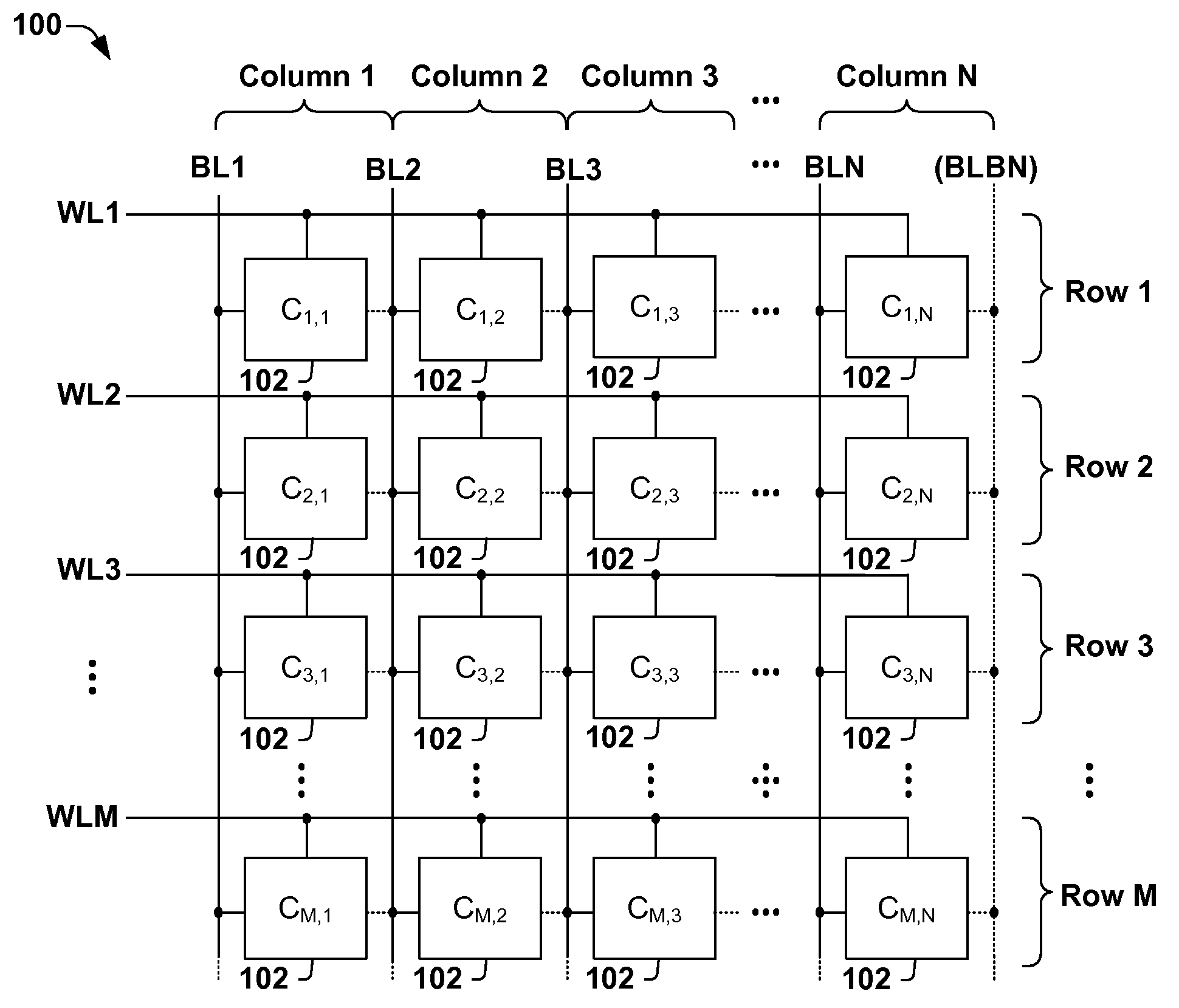
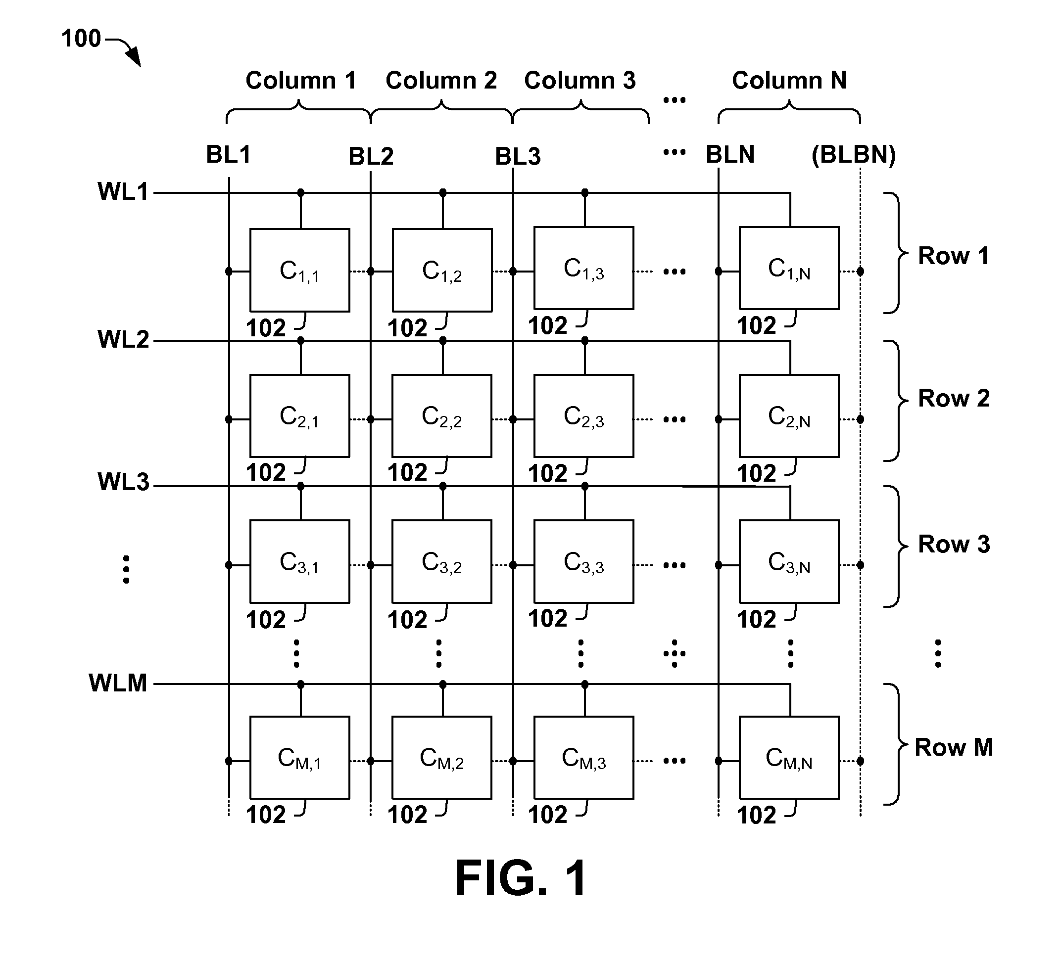
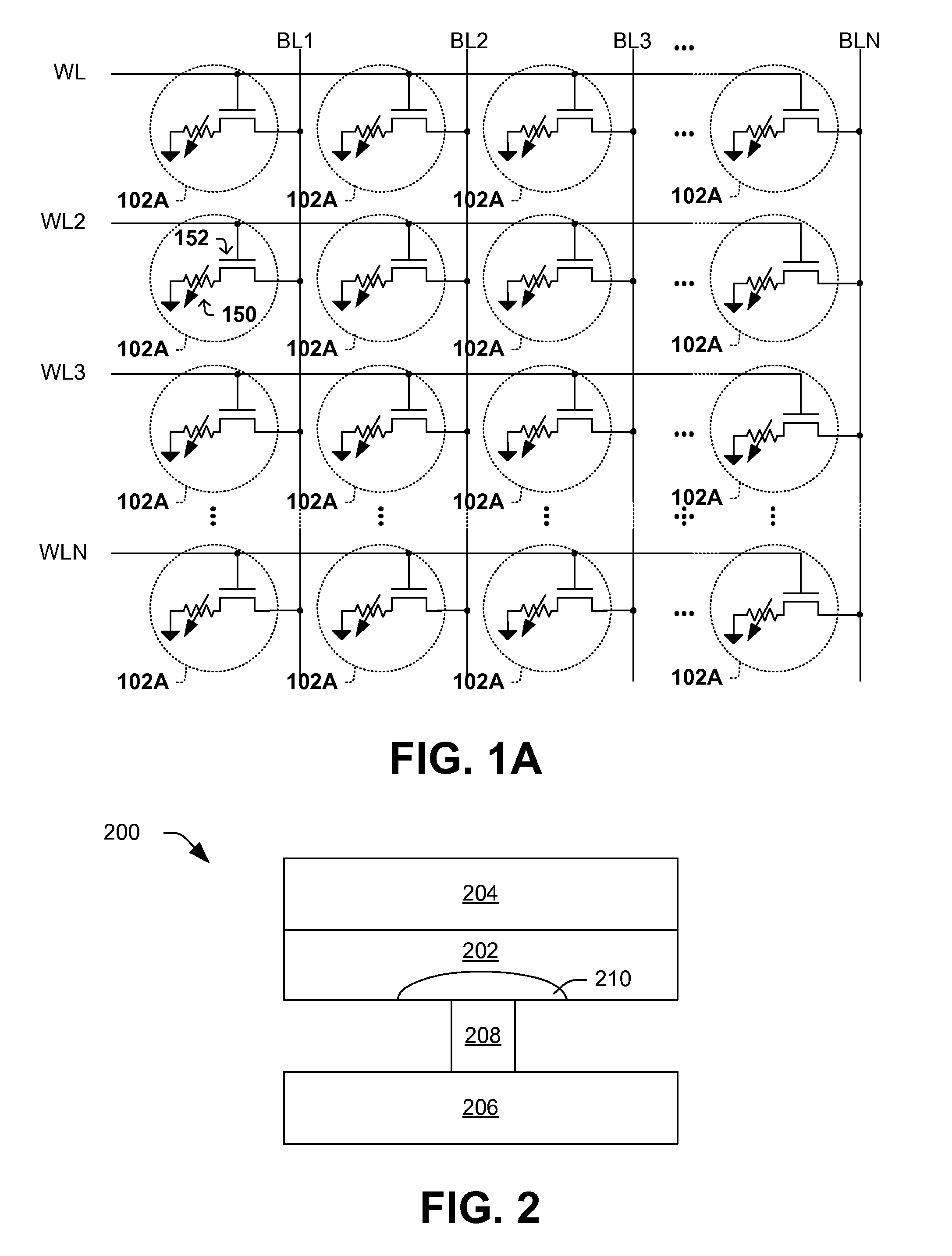
[0019]One or more implementations of the present invention will now be described with reference to the attached drawings, wherein like reference numerals are used to refer to like elements throughout. The drawings are not necessarily drawn to scale. Although various illustrated embodiments are described and illustrated as a hardware structure, the functionality and corresponding features of the present system can also be performed by appropriate software routines or a combination of hardware and software.

[0020]Although several embodiments are illustrated and discussed below in the context of resistive or phase-change memories, aspects of the present invention could also relate to other types of memory devices and methods associated therewith. Some examples of illustrative types of resistive memory include: perovskite memory, binary oxides random access memory (OxRAM), phase change random access memory (PCRAM), conductive bridging random access memory (CBRAM), and polymer memory. Oth...


PUM


Abstract

One embodiment of the invention relates to a method for repairing a memory array. In the method, a group of at least one memory cell is dynamically analyzed to determine whether the memory array includes at least one faulty cell that no longer properly stores data. If the group includes at least one faulty cell, at least the at least one faulty cell is associated with at least another cell. Other methods, devices, and systems are also disclosed.

Description

RELATED APPLICATION[0001]This application claims priority to U.S. Provisional Application Ser. No. 60 / 947,301 filed Jun. 29, 2007, entitled “MEMORY WITH DYNAMIC REDUNDANCY CONFIGURATION.”FIELD OF INVENTION[0002]The present invention relates generally to semiconductor devices and more particularly to improved methods and systems for semiconductor memories.BACKGROUND OF THE INVENTION[0003]Several trends presently exist in the semiconductor and electronics industry. One of these trends is that recent generations of portable electronic devices are using more memory than previous generations. This increase in memory allows these new devices to store more data, such as music or images, and also provides the devices with more computational power and speed.[0004]One type of memory device includes an array of resistive memory cells, where individual bits of data can be stored in the individual resistive memory cells of the array. Depending on how the cell is biased, it can be switched betwee...

Claims


Application Information

Patent Timeline
Patent Type & Authority Patents(United States)
IPC IPC(8): G11C11/00
CPCG11C11/5678G11C13/0007G11C13/0011G11C13/0014G11C13/0016G11C29/42G11C29/44G11C29/4401G11C29/76G11C2029/0409G11C2029/0411G11C2029/1208G11C2213/32
Inventor NIRSCHL, THOMASHAPP, THOMASPHILIPP, JAN BORIS
Owner INFINEON TECHNOLOGIES NORTH AMERICA CORPORATION
Why Eureka
Try Eureka