Image heating apparatus with frame accommodating apparatus components

a technology of heating apparatus and frame, applied in the field of image heating apparatus, can solve problems such as waste of energy, and achieve the effect of suppressing energy consumption and suppressing heat dissipation to the exterior

Inactive Publication Date: 2010-08-17
CANON KK
View PDF24 Cites 4 Cited by
  • Summary
  • Abstract
  • Description
  • Claims
  • Application Information

AI Technical Summary

Benefits of technology

[0024]Another purpose of the present invention is to provide an image heating apparatus, capable of suppressing energy consumption.

Problems solved by technology

Such construction inducing an easy heat transmission to the frame 5 results in a waste of energy.

Method used


Image

  • Image heating apparatus with frame accommodating apparatus components
  • Image heating apparatus with frame accommodating apparatus components
  • Image heating apparatus with frame accommodating apparatus components

Examples


exemplary embodiment 1

[0039](1) Image Forming Apparatus

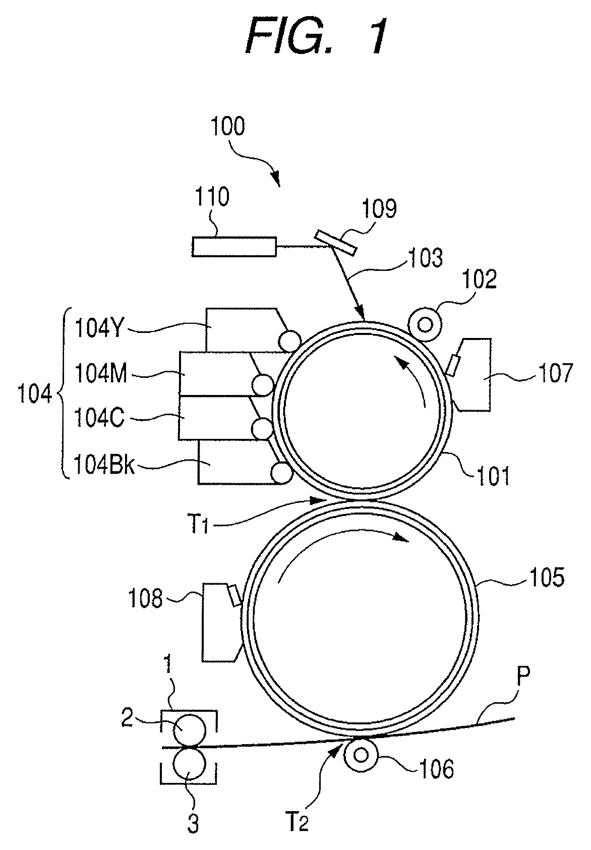
[0040]FIG. 1 illustrates schematic construction of a color laser beam printer of electrophotographic process, constituting an exemplary embodiment of an image forming apparatus 100.

[0041]Referring to FIG. 1, the image forming apparatus 100 includes an organic photosensitive member or an amorphous silicon photosensitive member of a drum shape (hereinafter called “photosensitive drum”) 101, serving as an image bearing member constituting an image forming unit. The photosensitive drum 101 is rotated, counterclockwise as indicated by an arrow, with a predetermined process speed (peripheral speed). As the image forming unit, there are provided, around the photosensitive drum 101, a charging roller 102 as a charging unit, a laser optics (laser scanner) 110 as an exposure unit, and a 4-color developing apparatus 104 as a development unit.

[0042]The photosensitive drum 101, in the course of rotation thereof, is subjected to a uniform charging of predetermined...

exemplary embodiment 2

[0100]In the following, a second exemplary embodiment of the fixing apparatus will be described with reference to FIGS. 6A and 6B. The entire constructions of the fixing apparatus of the present exemplary embodiment and of the image forming apparatus in which the fixing apparatus is applied, are made similar to those of the fixing apparatus and the image forming apparatus described in the exemplary embodiment 1. Therefore, in the apparatus of the present embodiment, a member equivalent in construction and function is represented by a same reference number, and the description in the exemplary embodiment 1 will be applied, without repeating the description again. FIGS. 6A and 6B illustrate the pressurizing rotary member 3 only, omitting the heat source-side rotary member unit 2.

[0101]The fixing apparatus 1 of the present exemplary embodiment is equipped, in addition to the structure of the apparatus of the embodiment 1, with a heat shield cover 202 also on the pressure roller 3 servi...

exemplary embodiment 3

[0111]Now a third exemplary embodiment of the fixing apparatus of the present invention will be described with reference to FIGS. 7 and 8. The entire constructions of the fixing apparatus of the present exemplary embodiment and of the image forming apparatus in which the fixing apparatus is applied, are made similar to those of the fixing apparatus and the image forming apparatus described in the exemplary embodiment 1. Therefore, in the apparatus of the present embodiment, a member equivalent in construction and function is represented by a same reference number, and the description in the exemplary embodiment 1 will be applied, without repeating the description again.

[0112]In the exemplary embodiments 1 and 2, there has been described a fixing apparatus of film heating type, utilizing a ceramic heater 15. The fixing apparatus of the present exemplary embodiment is of heat roller type, equipped, as the heat source-side rotary member unit, with a fixing roller 4 incorporating a heat...


PUM


Abstract

The image heating apparatus includes a rotary member that comes into contact with a toner image borne on a recording material, a backup member that forms a nip portion to pinch and convey the recording material with said rotary member, wherein said rotary member heats the toner image on the recording material in the nip portion, a cover member that covers a surface of said rotary member with a gap between the surface of said rotary member and the cover member and a frame that accommodates said rotary member, said backup member and said cover, wherein said cover is not in contact with said frame. This structure can suppress heat dissipation to the exterior of the image heating apparatus, thus suppressing the energy consumption.

Description

BACKGROUND OF THE INVENTION[0001]1. Field of the Invention[0002]The present invention relates to an image heating apparatus adapted for use as a heat fixing apparatus to be mounted on an image forming apparatus such as a copying machine or a printer utilizing electrophotographic recording technology.[0003]2. Description of the Related Art[0004]In a prior image forming apparatus, an image is formed on an image bearing member by an appropriate image forming process such as an electrophotographic process, then such image is either directly or indirectly borne on a recording material, and such unfixed image (toner image) is heat fixed, by a fixing apparatus, on the surface of the recording material as a permanently fixed image. For such fixing apparatus, an apparatus of heat roller type has been widely utilized. Also in recent years, an apparatus of film heating type has been commercialized from the standpoints of quick starting and energy saving. Also proposed is an apparatus of electr...

Claims


Application Information

Patent Timeline
Patent Type & Authority Patents(United States)
IPC IPC(8): G03G15/20
CPCG03G15/2064G03G2215/2016G03G2215/2035
Inventor MIKI, TSUTOMUKEMMOCHI, KAZUHISAOSADA, HIKARUUMEZAWA, MASAO
Owner CANON KK
Why Eureka
Try Eureka