
Porous member

A porous and component technology, used in ceramic products, other household appliances, transportation and packaging, etc., can solve the problems of large dielectric loss, decreased yield of semiconductor products, unstable plasma, etc., to achieve uniform dispersion and restrain energy consumption. Effect

Active Publication Date: 2009-04-29
TOHOKU UNIV +1
View PDF2 Cites 1 Cited by
  • Summary
  • Abstract
  • Description
  • Claims
  • Application Information

AI Technical Summary

Problems solved by technology

[0006] However, in parts using conventional porous members, the dielectric loss tangent of the material is large, which leads to microwave loss, plasma instability, and a decrease in the yield of semiconductor products.
Moreover, since the porosity and pore diameter cannot be sufficiently controlled, it is difficult to control a stable gas flow rate

Method used

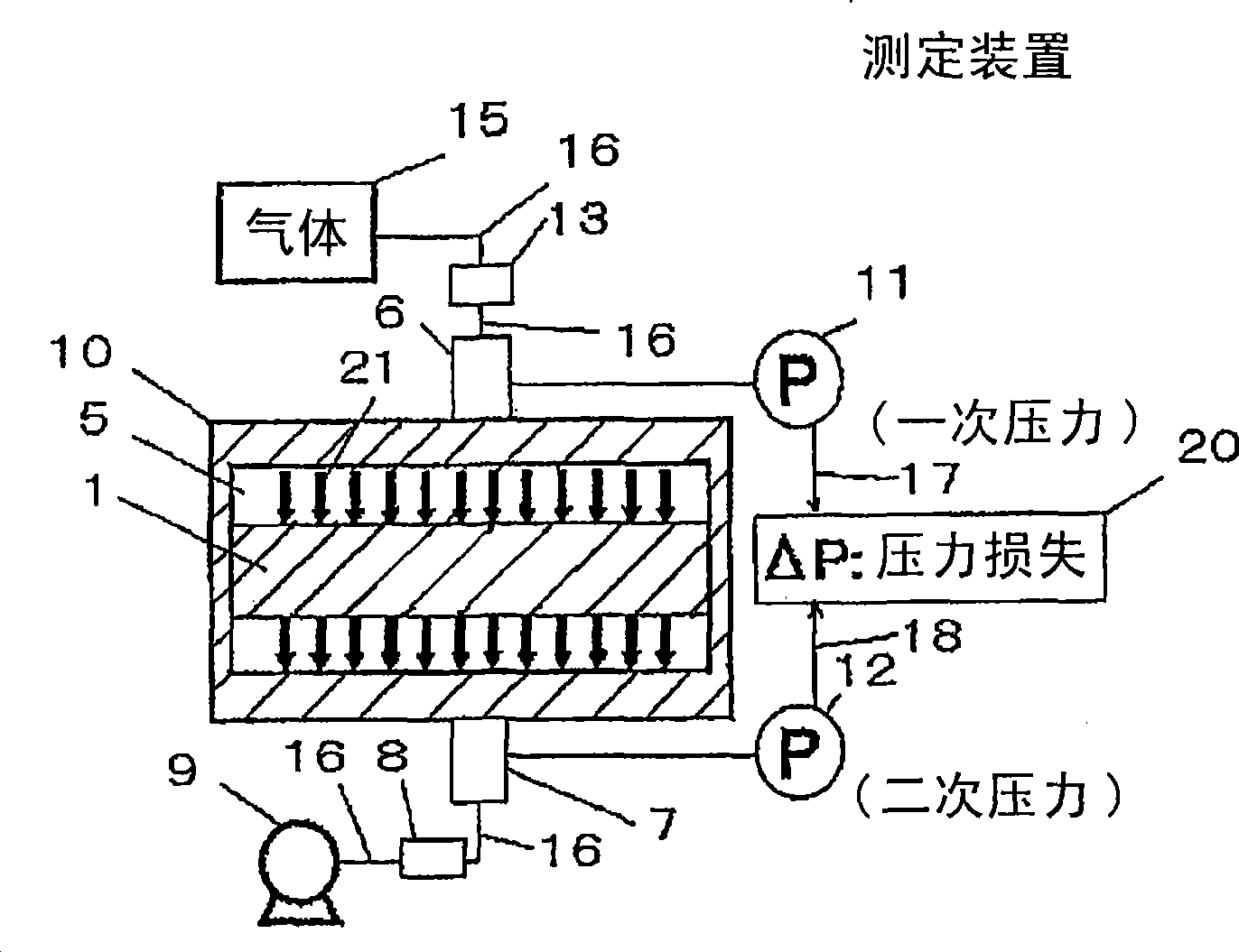
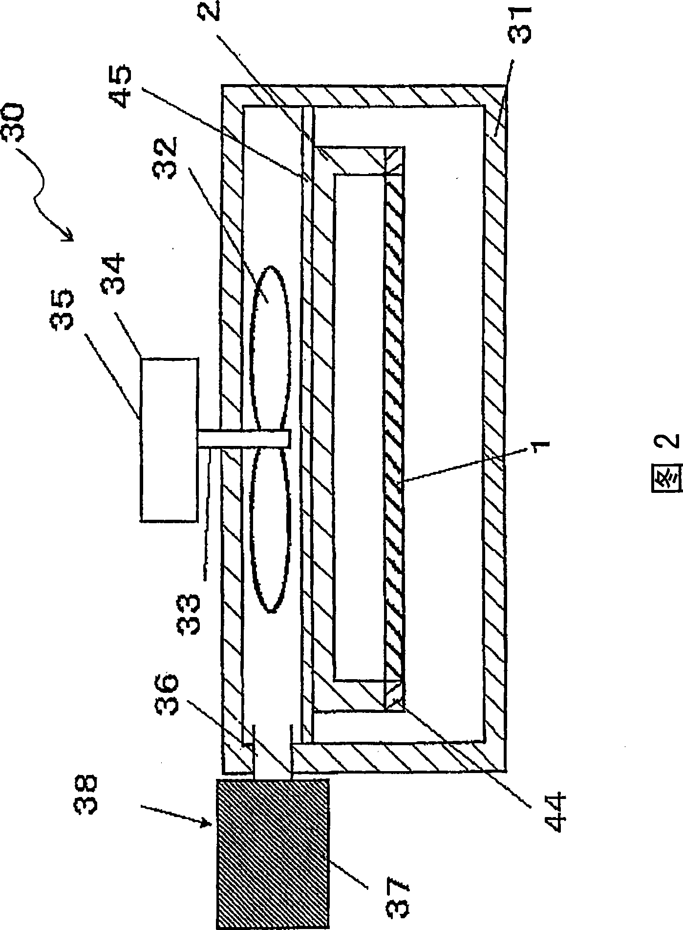
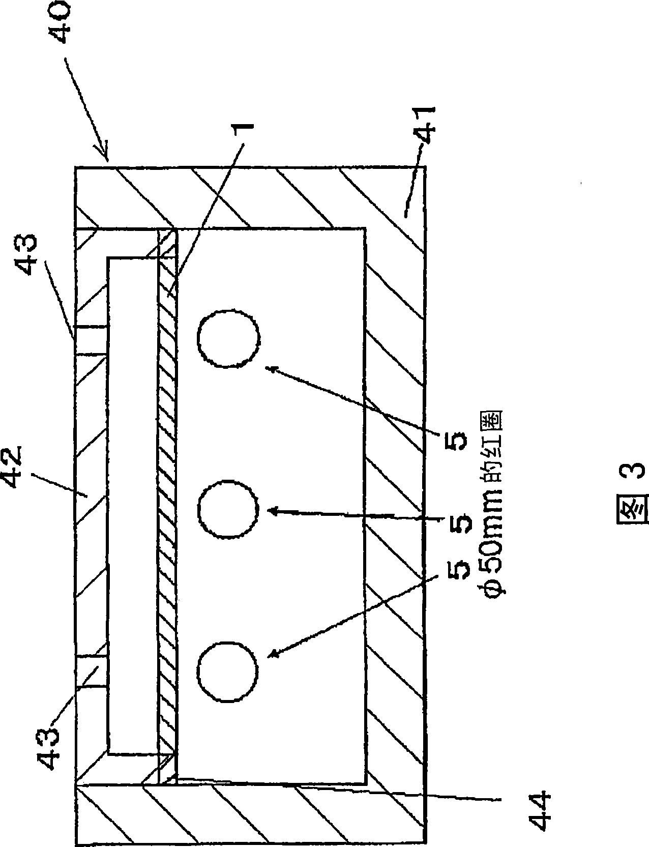

Image

  • Porous member
  • Porous member
  • Porous member

Examples


Embodiment

[0068] Next, examples of the present invention will be given. In the following examples, although examples 1 to 4 are preferable, it goes without saying that the present invention is not limited to these examples.

[0069] The material particle type / purity / particle size of the raw materials used to produce the porous member of the present invention, the type of bonding material / the compounding ratio of material particles are shown in Table 1 below. The types of material particles are alumina, quartz, and yttrium oxide, the purity is more than 99%, and the particle size is 1-300 μm. Quartz with a purity of more than 99% or alkali-free glass with a low alkali content is used as the bonding material.

[0070] The material particles and the bonding material are weighed in a predetermined ratio, and a mixed slurry of the material particles and the bonding material is prepared by a ball mill using resin balls in ion-exchanged water. This was poured into a mold of □200×t50 mm made ...


PUM

PropertyMeasurementUnit
pore sizeaaaaaaaaaa
particle sizeaaaaaaaaaa

Abstract

This invention provides a porous member that, when used in a field requiring a high level of cleanness, can suppress energy loss in a microwave band and can evenly disperse gas. The porous member is formed of a porous ceramic and has a dielectric loss tangent at a microwave band of not more than 1x10<-3>. A ceramic member comprising a ceramic sinter comprising this porous member in a part thereof is also provided.

Description

technical field [0001] The present invention relates to a porous member, which is used for parts and members used in environments requiring energy saving and uniform gas flow, such as dry preparation of electronic devices, manufacture of medical drugs, and food processing. Background technique [0002] With the improvement of the integration level of semiconductors, the miniaturization of design rules is progressing, and the size and number of allowable deposits and metal contamination are required to be reduced and reduced. [0003] On the other hand, as equipment for manufacturing semiconductors, in order to improve efficiency, a plasma excitation method based on microwaves has been adopted. Even in the fields of medicine and food, microwaves can be used in processes such as drying, and ceramics are usually used for these structures to prevent contamination from metals and the like. [0004] Here, as a semiconductor manufacturing facility, a microwave plasma processing de...

Claims


Application Information

Patent Timeline
Patent Type & Authority Applications(China)
IPC IPC(8): C04B38/00
CPCC04B2235/3418C04B38/0058C04B2235/72C04B2235/5445C04B2235/77C04B2235/36C04B2235/656C04B2235/5427C04B2235/5436C04B35/6316C04B35/505C04B35/111Y10T428/249921C04B35/00C04B38/0054C04B38/00
Inventor 大见忠弘岸幸男井口真仁市川佳孝小松祐介
Owner TOHOKU UNIV
Learn More