Stepping motor control circuit and analog electronic timepiece
a technology of analog electronic timepiece and control circuit, which is applied in the direction of programme control, dynamo-electric converter control, instruments, etc., can solve the problems of unnecessari consumption of driving energy and dramatic consumption of secondary cell energy, so as to prevent non-rotation, suppress energy consumption, and suppress energy consumption
- Summary
- Abstract
- Description
- Claims
- Application Information
AI Technical Summary
Benefits of technology
Problems solved by technology
Method used
Image
Examples
first embodiment
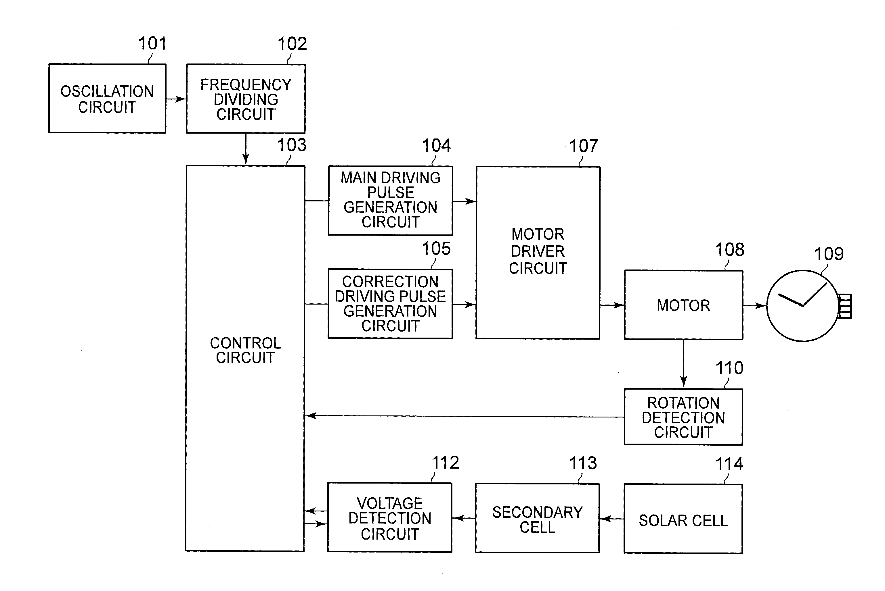
[0065]FIG. 4 is a flowchart illustrating the operations of the stepping motor control circuit and the analog electronic timepiece according to the invention and is a flowchart mainly illustrating an operation of the control circuit 103.
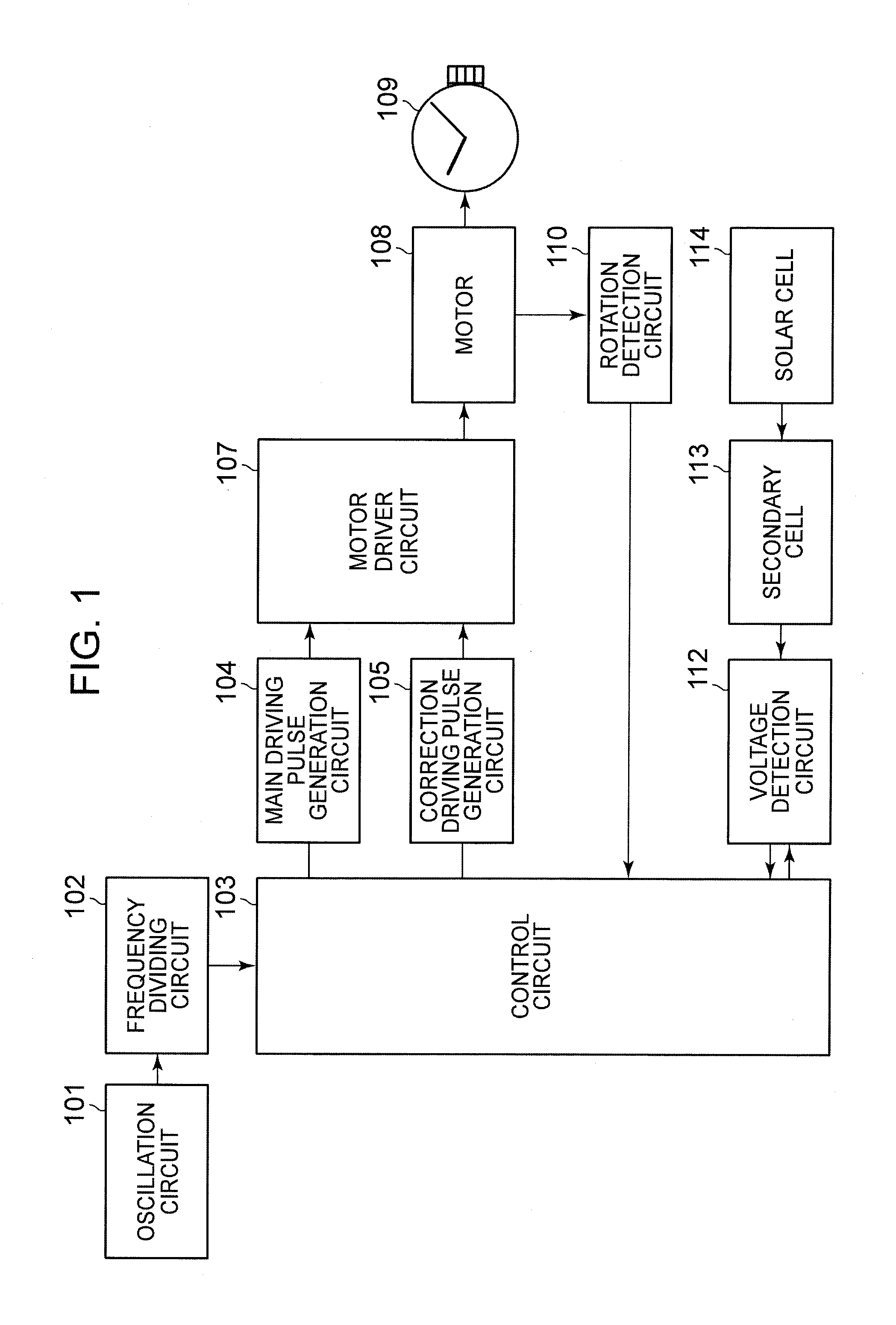
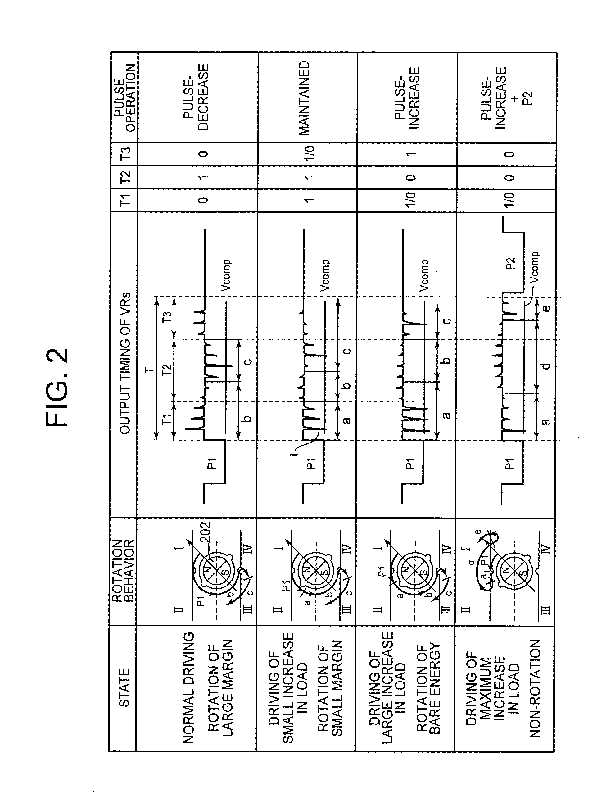
[0066]Hereinafter, an operation of the first embodiment of the invention will be described in detail with reference to FIGS. 1 to 4. In the initial state, the first reference voltage Lo of the low level is set as the switch voltage.
[0067]The control circuit 103 resets a rank n of the main driving pulse P1 to 0 (main driving pulse P10) with the minimum energy and resets the value of a continuous driving number of times N to 0 (step S501).
[0068]Next, the control circuit 103 allows the voltage detection circuit 112 to detect the voltage of the secondary cell 113 and determines whether the voltage detection circuit 112 detects the switch voltage (here, the first reference voltage Lo), that is, whether the voltage of the secondary cell 113 is lowered to a ...
second embodiment
[0105]The analog electronic timepiece according to the invention includes the stepping motor 108 that rotatably drives a time pointer and the stepping motor control circuit that controls the stepping motor 108. The above-described stepping motor control circuit serves as the stepping motor control circuit. Therefore, since the stepping motor 108 is driven by the main driving pulse P1 in accordance with the voltage of the secondary cell 113 and the rotation state of the stepping motor 108, the non-rotation can be prevented. Further, since the energy consumption is suppressed, it is possible to obtain the advantage of performing accurate pointer movement.
[0106]Next, a third embodiment of the invention will be described. The block diagram of the third embodiment is the same as the block diagram of FIG. 1.
[0107]In the first and second embodiments described above, two kinds of modes are provided. That is, the first mode is provided in which the driving is performed using one kind of main...
third embodiment
[0112]The driving pulses with various energies can be used as the main driving pulse P1 used in the first mode. In the third embodiment, the main driving pulse with the maximum energy in the second main driving pulse group is used as the main driving pulse P1 used in the first mode. In the first mode, when it is determined that the driving energy is large and the pulse-decreases is necessary, the control mode is changed to the third mode in which the driving is performed using the second main driving pulse group.
[0113]FIG. 6 is a diagram illustrating timings when the stepping motor 108 is driven by the main driving pulse P1 in the third mode according to the third embodiment of the invention.
[0114]In the third mode, the detection section T immediately after the driving of the main driving pulse 21 is divided into a fourth section T11, a fifth section TS which is a predetermined time after the fourth section T11, a sixth section T21 which is a predetermined time after the fifth secti...
PUM
 Abstract
Description
Claims
Application Information
 - R&D
- Intellectual Property
- Life Sciences
- Materials
- Tech Scout
- Unparalleled Data Quality
- Higher Quality Content
- 60% Fewer Hallucinations
Browse by: Latest US Patents, China's latest patents, Technical Efficacy Thesaurus, Application Domain, Technology Topic, Popular Technical Reports.
© 2025 PatSnap. All rights reserved.Legal|Privacy policy|Modern Slavery Act Transparency Statement|Sitemap|About US| Contact US: help@patsnap.com


