
Water treatment method and water treatment device

A water treatment device and water treatment technology, applied in biological treatment devices, biological treatment adjustment methods, water treatment parameter control, etc., can solve the problems of increased import costs and inability to increase sludge concentration, etc.

Pending Publication Date: 2020-09-15
ORGANO CORP
View PDF9 Cites 0 Cited by
  • Summary
  • Abstract
  • Description
  • Claims
  • Application Information

AI Technical Summary

Problems solved by technology

In order to introduce such a deep tank reaction tank, it is necessary to carry out a large-scale renovation work on the main body of the reaction tank, and there is a problem of increasing the introduction cost in a large-scale treatment plant such as sewage.
In addition, in order to further improve the effect, it is necessary to increase the sludge concentration and increase the MLSS (for example, 2000 mg / L or more in terms of MLSS), but there is a problem that the sludge concentration cannot be increased from the viewpoint of the solid-liquid separation of sludge

Method used


Image

  • Water treatment method and water treatment device
  • Water treatment method and water treatment device
  • Water treatment method and water treatment device

Examples


Embodiment approach 1

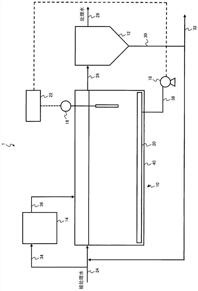
[0051] The water treatment device 1 is a water treatment device that treats treated water containing organic matter and nitrogen components. It has: a biological treatment device 10, which has at least an aerobic tank 40 and a blower 18, wherein the blower 18 is used to In the oxygen-containing gas supply unit for supplying oxygen-containing gas to the aerobic tank 40, the above-mentioned biological treatment device 10 is used to biologically treat the incoming water to be treated in an aerobic manner through the sludge containing particles; the solid-liquid separation device 12 , which is to carry out solid-liquid separation of the biological treatment liquid in the aerobic tank 40, and separate it into a solid-liquid separation unit for treating water and concentrated sludge; Thickened sludge is sent back to the sludge return unit at the front stage of the biological treatment device 10; the ammoniacal nitrogen concentration measuring device 16 is used to measure the ammoniac...

Embodiment approach 2

[0072] figure 1 In the water treatment device 1 , the water to be treated containing organic matter, nitrogen components, and phosphorus is supplied to the aerobic tank 40 of the biological treatment device 10 through the water to be treated pipe 24 . The aerobic tank 40 is a continuous reaction tank for treating organic matter and phosphorus with a pseudo-AO method (pseudo-anaerobic-aerobic activated sludge method) as the target, and the blower 18 supplies air and the like through the aeration device 20. Oxygen gas is used to aerate and maintain an aerobic state while stirring the tank, but stop or weaken aeration at the front end (inflow portion) of the tank to maintain an anaerobic state. On the other hand, part of the water to be treated is supplied to the granule formation tank 14 through the water to be treated pipe 34, and granules containing polyphosphoric acid accumulation bacteria are formed in the granule formation tank 14 (particle formation process), and the forme...

Embodiment approach 3

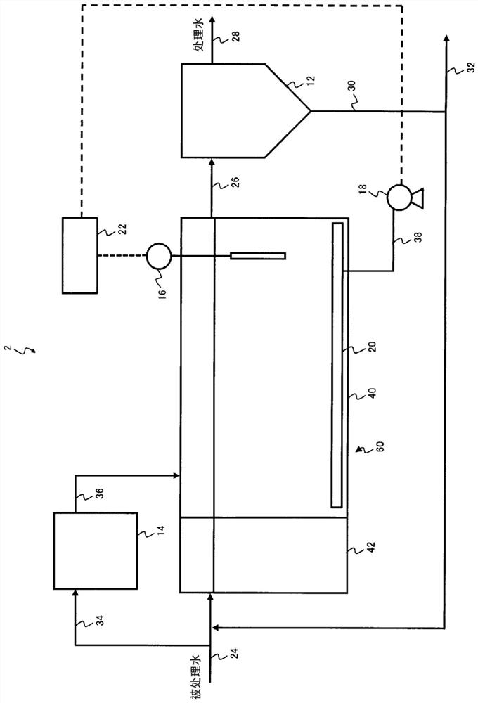
[0079] figure 2 In , the schematic structure of another example of the water treatment apparatus concerning embodiment of this invention is shown. figure 2 The water treatment device 2 has: biological treatment device 60, which has anaerobic tank 42, aerobic tank 40 and blower 18; solid-liquid separation device 12; sludge returns to piping 30; ammoniacal nitrogen concentration measuring device 16; and control device 22. The water treatment device 1 may have a particle formation tank 14 provided outside the biological treatment device 60 .

[0080] figure 2 In the water treatment device 2, the water to be treated pipe 24 is connected to the water to be treated inlet of the anaerobic tank 42 of the biological treatment device 60. The outlet of the aerobic tank 40 and the inlet of the solid-liquid separator 12 are connected by a biological treatment liquid pipe 26 . A treated water pipe 28 is connected to the treated water outlet of the solid-liquid separator 12 . The slu...


PUM

PropertyMeasurementUnit
particle diameteraaaaaaaaaa
concentrationaaaaaaaaaa

Abstract

Provided are a water treatment method and a water treatment device that can be introduced in a standard tank with an effective water depth of 5 m or less during treatment of water to be treated that contains organic matter and a nitrogen component, and that allow improvement in efficiency of removing nitrogen from the water to be treated and suppressing energy consumption for aeration while maintaining a high MLSS. The water treatment method is for treating water to be treated that contains organic matter and a nitrogen component, and includes, in a biological treatment device (10) comprisingat least an aerobic tank (40): a biological treatment step for biologically treating inflowing water to be treated aerobically by using sludge that contains granules; a solid-liquid separation step for separating the biological treatment solution in the aerobic tank (40) into treated water and concentrated sludge using a solid-liquid separation device (12); and a sludge return step for returning the concentrated sludge obtained in the solid-liquid separation step to a stage before the biological treatment device (10). The concentration of ammonia nitrogen remaining due to the nitrification reaction in the aerobic tank (40) is measured with an ammonia nitrogen concentration measurement device (16), and the amount of gas containing oxygen dispersed to the aerobic tank (40) is controlled witha blower (18) so that the measured ammonia nitrogen concentration is within a prescribed range.

Description

technical field [0001] The present invention relates to a water treatment method and a water treatment device for treating water to be treated containing organic matter and nitrogen components. Background technique [0002] In the biological water treatment of wastewater such as sewage, an activated sludge method using aggregates of microorganisms called flocs (aerobic biological sludge) is used. The activated sludge method is to supply oxygen to the activated sludge in the biological reaction tank while the wastewater flows into the biological reaction tank, so as to use various metabolisms of aerobic microorganisms in the activated sludge to convert the waste water into The aerobic biological treatment method that decomposes the organic matter and obtains clear treated water, especially in sewage treatment, the activated sludge method is a widely used treatment method. [0003] As one of the subjects of the activated sludge method which is an aerobic biological treatment ...

Claims


Application Information

Patent Timeline
Patent Type & Authority Applications(China)
IPC IPC(8): C02F3/34C02F3/10C02F3/12
CPCY02W10/10C02F3/006C02F3/301C02F3/302C02F2203/004C02F2209/14C02F2209/15C02F2209/22C02F2209/38C02F3/1263C02F3/12C02F2101/16
Inventor 三宅将贵长谷部吉昭
Owner ORGANO CORP
Learn More