Apparatus for heat-treating toner and method for producing toner

a technology of toner and apparatus, applied in the field of apparatus for heat-treating toner, can solve the problems of increasing the amount of heat consumed, so as to reduce the energy required for heat treatment, reduce environmental load, and reduce the effect of energy consumption

Active Publication Date: 2012-09-13
CANON KK
View PDF1 Cites 2 Cited by
  • Summary
  • Abstract
  • Description
  • Claims
  • Application Information

AI Technical Summary

Benefits of technology

[0009]According to aspects of the present invention, electricity required for the heat treatment can be reduced du...

Problems solved by technology

Energy consumption and improvement in thermal energy efficiency are issues of concern.
In the apparatus for heat-treating toner described in Japanese Patent Laid-Open No. 2004-189845, a high flow rate of hot air having a high tempe...

Method used


Image

  • Apparatus for heat-treating toner and method for producing toner
  • Apparatus for heat-treating toner and method for producing toner
  • Apparatus for heat-treating toner and method for producing toner

Examples


example 1

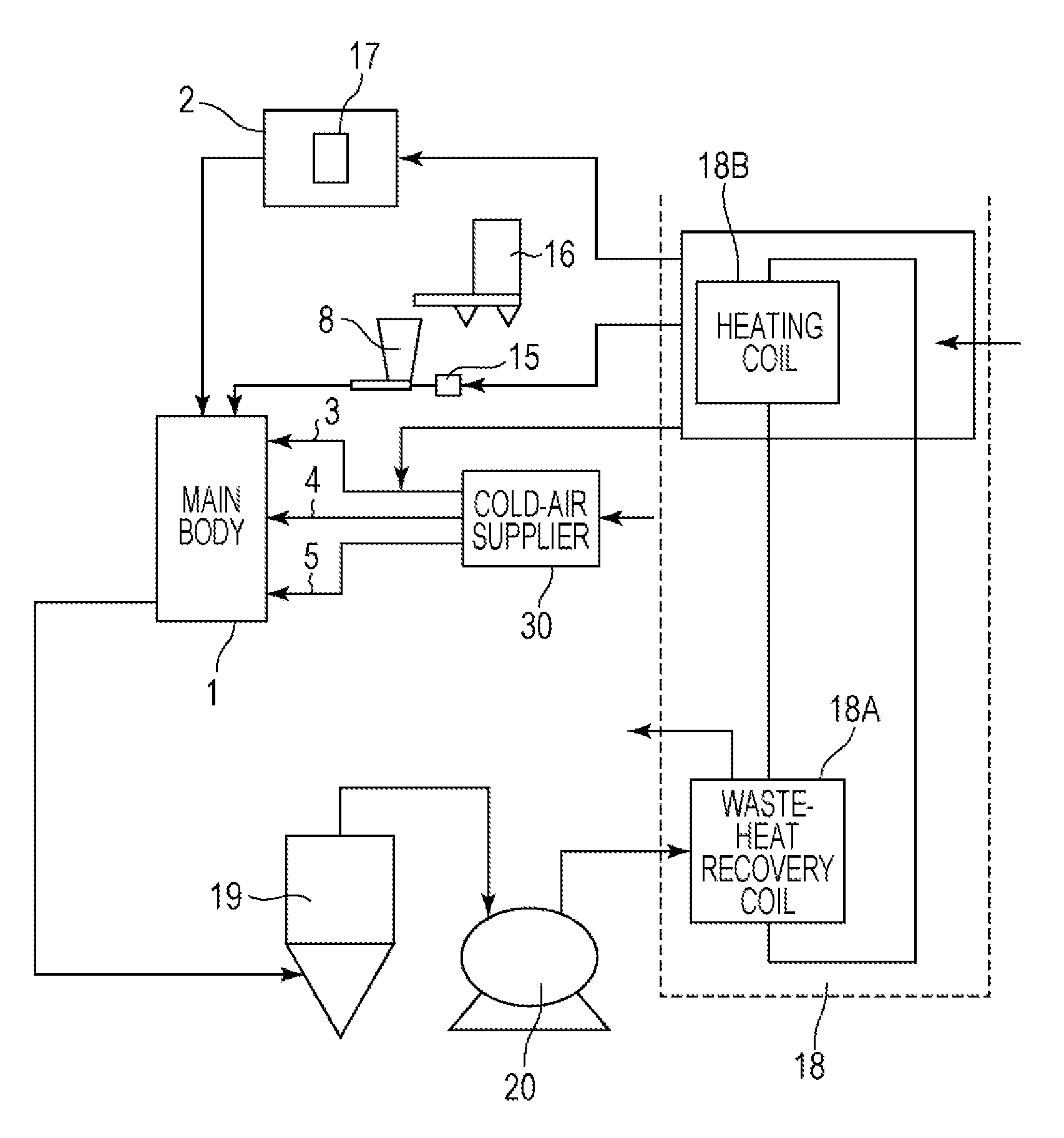
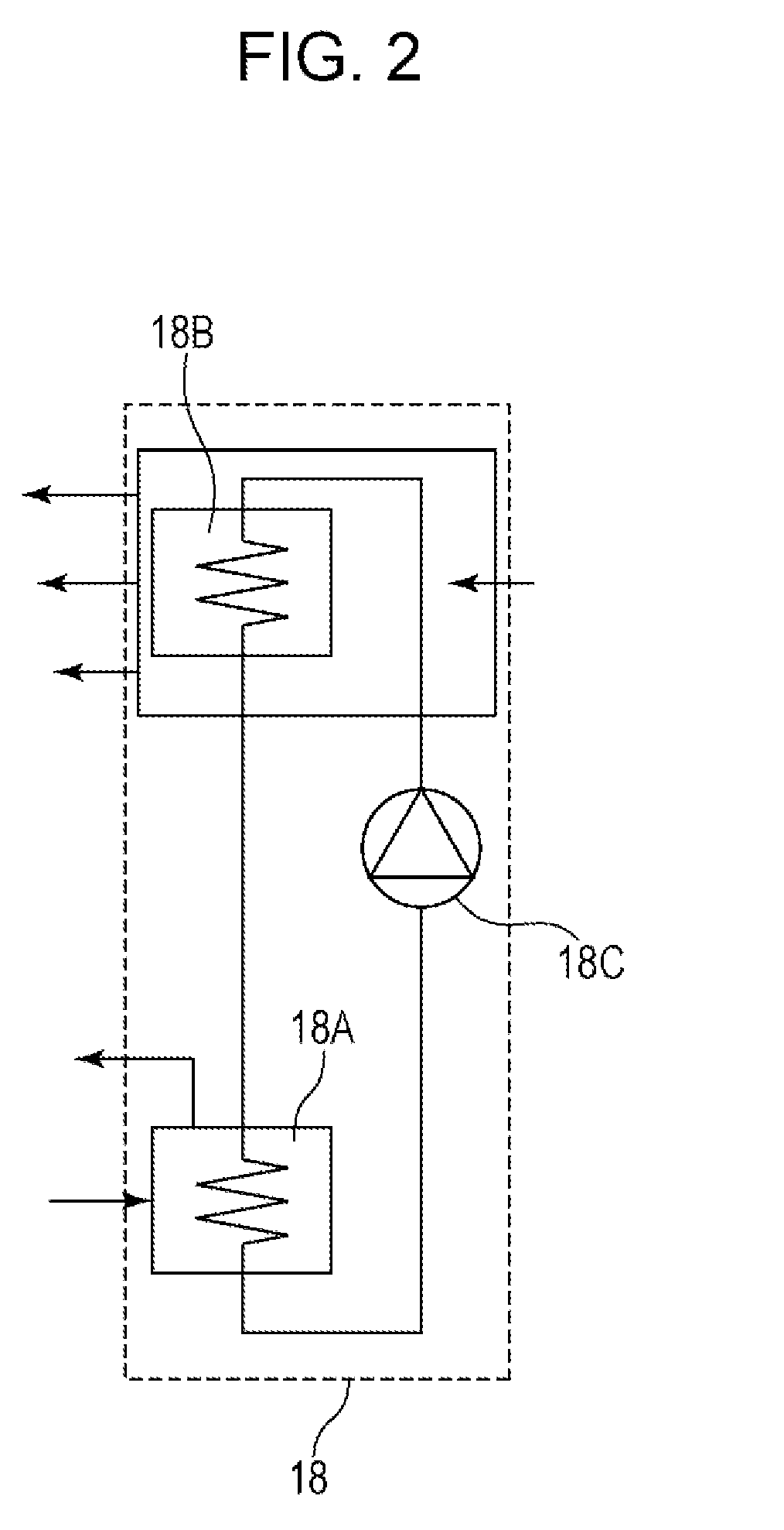
[0097]In this example, the apparatus for heat-treating a toner had a structure such that heat recovered by the waste-heat recovery and supply unit was used for the hot-air supply unit, the first cold-air supply unit, and the raw-material supply unit on the basis of the production procedure illustrated in FIG. 1. The main body of the heat-treatment apparatus illustrated in FIGS. 4A to 4C was used. Toner particles A (raw-material toner) were heat-treated with the apparatus for heat-treating a toner described above.

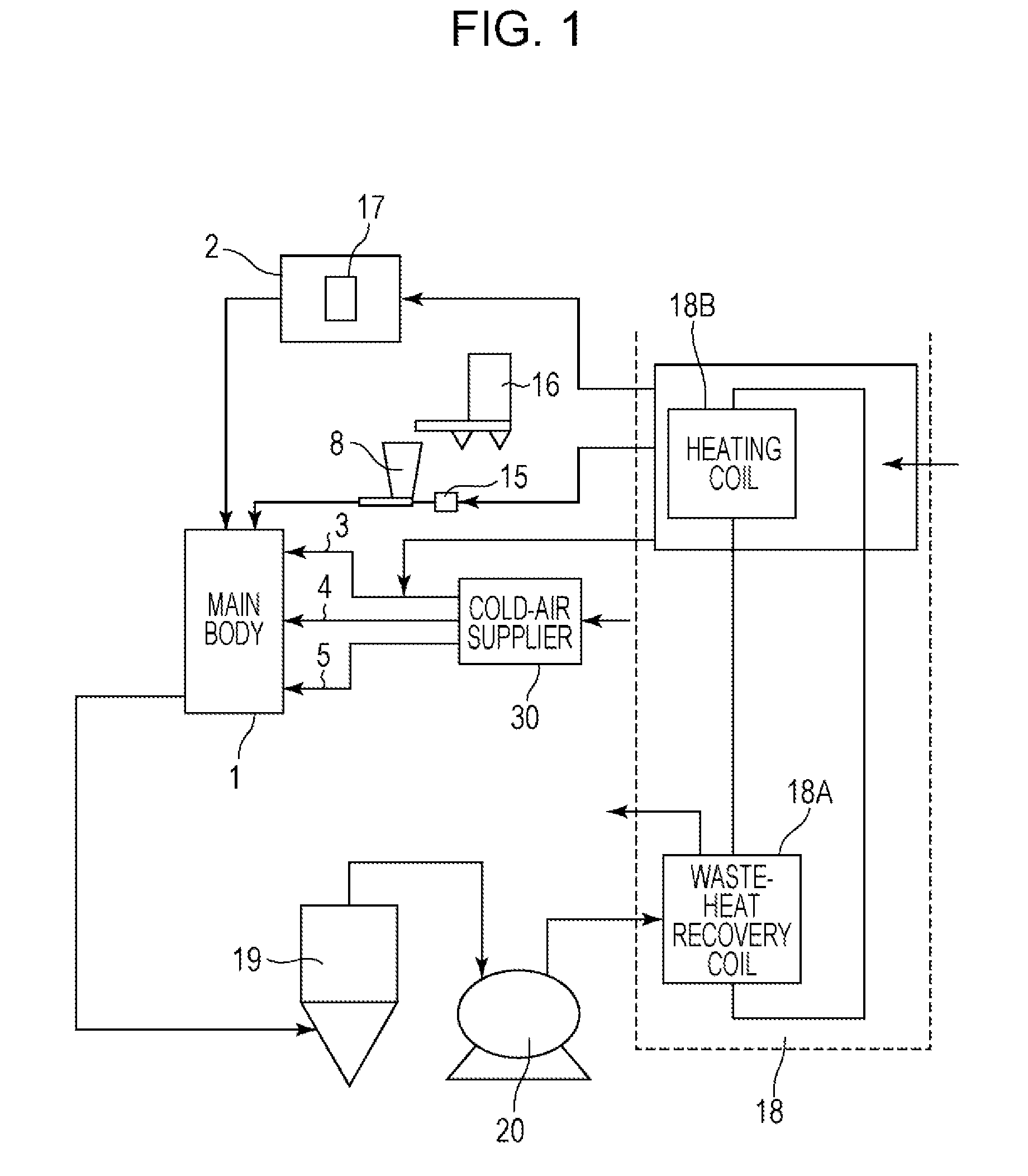
[0098]The waste-heat recovery and supply unit illustrated in FIG. 2 had a recovery capacity of 10 kW. The heater used in the hot-air supply unit had a rated heater capacity of 115 kW.

[0099]The throughput was 15 kg / hr. The operating time was 6 hours after the hot-air temperature was stabilized and the liquid temperature in the waste-heat recovery and supply unit was also stabilized. Furthermore, operating conditions were adjusted in such a manner that treated toner particles ...

example 2

[0103]In this example, with respect to the production procedure illustrated in FIG. 1, heat recovered was used for the hot-air supply unit and the raw-material supply unit. Toner particles A were heat-treated as in EXAMPLE 1 in such a manner that heat-treated toner particles A had an average circularity of 0.970, except that the operating conditions were changed as described in Table 1. Table 2 illustrates the operation results.

[0104]The resulting toner particles had a weight-average particle size of 5.9 μm, in which the proportion of particles having a particle size of 4.0 μm or less was 24.2% by number, and the proportion of particles having a particle size of 10.0 μm or more was 2.1% by volume.

example 3

[0105]In this example, with respect to the production procedure illustrated in FIG. 1, heat recovered was used for the hot-air supply unit. Toner particles A were heat-treated as in EXAMPLE 1 in such a manner that heat-treated toner particles A had an average circularity of 0.970, except that the operating conditions were changed as described in Table 1. Table 1 illustrates the operating conditions. Table 2 illustrates the operation results.

[0106]The resulting toner particles had a weight-average particle size of 6.0 μm, in which the proportion of particles having a particle size of 4.0 μm or less was 24.0% by number, and the proportion of particles having a particle size of 10.0 μm or more was 2.8% by volume.


PUM


Abstract

An apparatus for heat-treating a toner includes a raw-material supply unit configured to supply a toner treatment space with a raw-material toner, a hot-air supply unit configured to heat-treat the raw-material toner in the toner treatment space, a suction and ejection unit configured to eject hot air used for the heat treatment of the raw-material toner, and a waste-heat recovery and supply unit configured to recover heat from the hot air ejected by the suction and ejection unit and supply the hot-air supply unit with the recovered heat.

Description

BACKGROUND OF THE INVENTION[0001]1. Field of the Invention[0002]The present invention relates to an apparatus for heat-treating a toner, the apparatus being used to produce a toner for use in an image forming method, for example, an electrophotographic method, an electrostatic recording method, an electrostatic printing method, or a toner jet recording method, and relates to a method for producing a toner.[0003]2. Description of the Related Art[0004]Hitherto, apparatuses for heat-treating toner have been used in processes for producing toner in order to form toner particles into a spherical shape. In apparatuses for heat-treating toner in the related art, techniques for heating and forming toner particles into a spherical shape using hot air are used. In such an apparatus for heat-treating toner, typically, outside air is taken and heated with, for example, a heater to produce hot air.[0005]Japanese Patent Laid-Open No. 2004-189845 discloses a heat-treatment apparatus for heat-treat...

Claims


Application Information

Patent Timeline
IPC IPC(8): G03G9/00
CPCG03G9/0808G03G9/0815G03G9/081G03G9/08G03G9/087
Inventor MINAGAWA, HIRONORIMIZO, YUICHIOOTSU, TAKESHIHAGIWARA, JUNICHIITO, DAISUKEKAWAKITA, KUNIHIKOTAMURA, YASUSHI
Owner CANON KK
Why Eureka
Try Eureka