Polymer object optical fabrication process

a technology of optical fabrication and polymer objects, applied in the field of microstereolithography, can solve the problems of not incorporating projection technology into the two-photon fabrication process, system limitation in the volume of fabrication, and speed of scanning mirror systems, so as to reduce or eliminate the need for support structures, the effect of rapid prototyping

Inactive Publication Date: 2010-08-17
POOF TECH LLC
View PDF5 Cites 25 Cited by
  • Summary
  • Abstract
  • Description
  • Claims
  • Application Information

AI Technical Summary

Benefits of technology

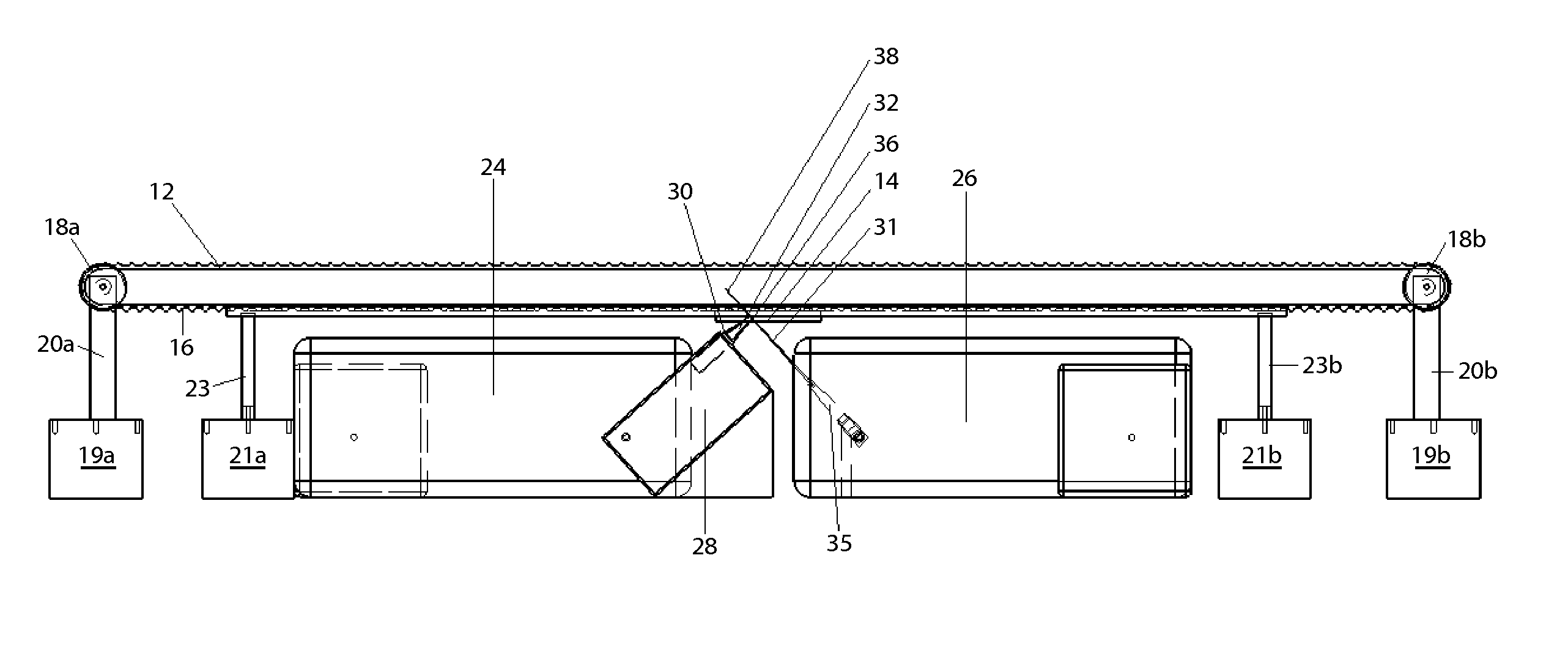
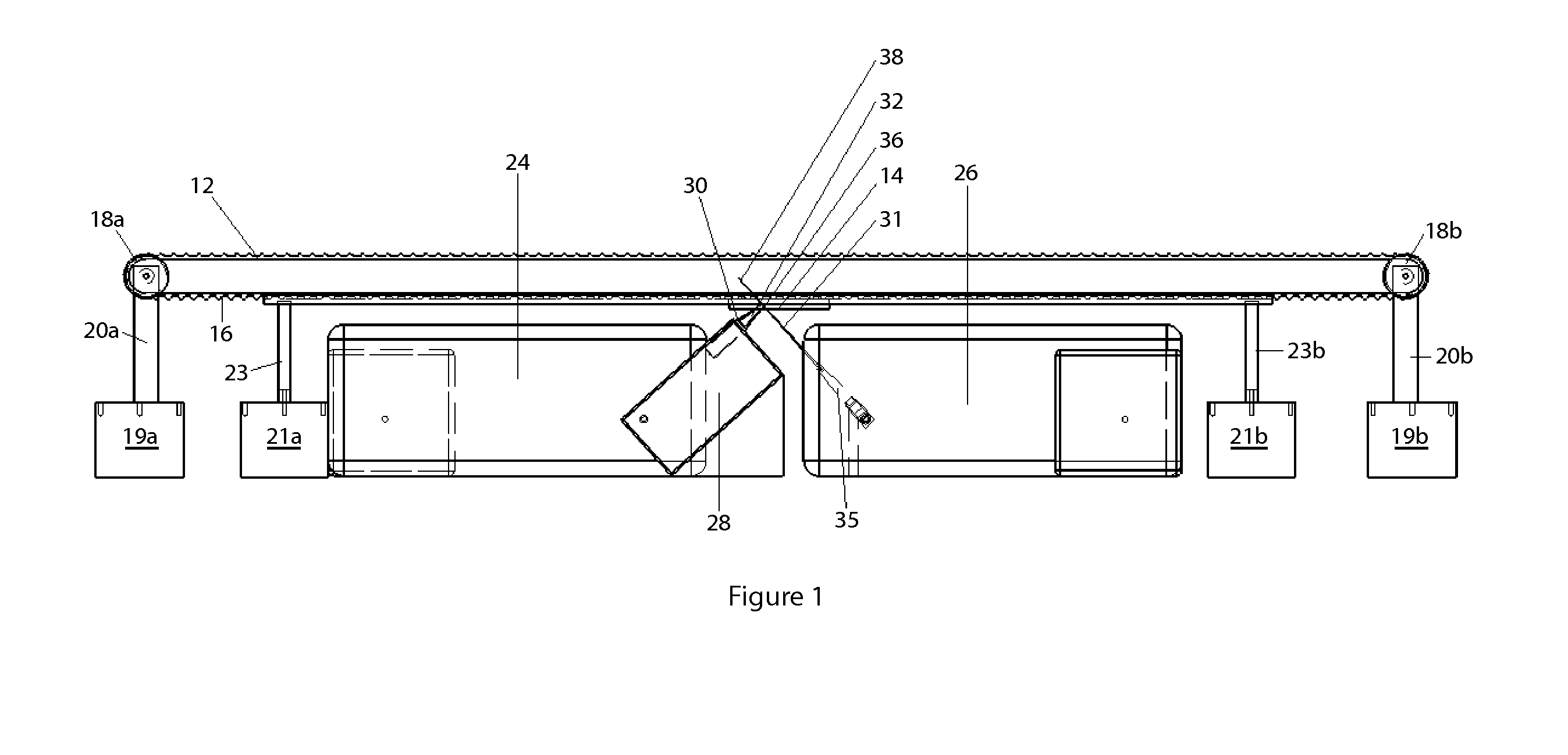
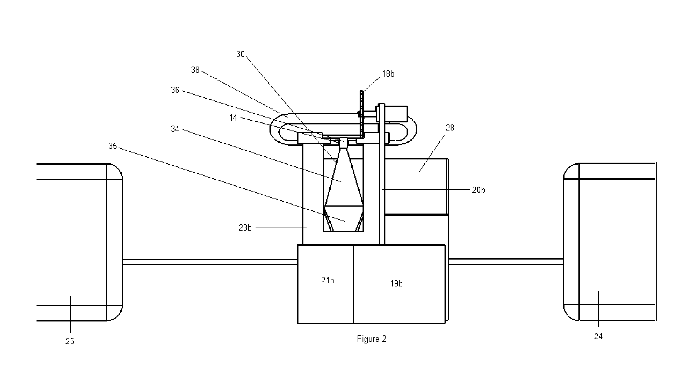
[0018]The POOF process further evolves the known stereolithography process by taking a projection-based, non-degenerate two photon induced photopolymerization (TPIP) approach to stereolithography. Incorporating a spatial light modulator such as Texas Instrument's Digital Light Processor (DLP™) projection technology into the two-photon fabrication process introduces a highly parallel approach to microstereolithography that substantially reduces or eliminates the need for support structure, provides unlimited part geometrical complexity (within a finite range of micro resolution smallest feature sizes) in resulting parts, and provides the optical and mechanical configuration that enables rapid prototyping, high-volume mass-production, and mass-customization of micro polymer and micro-polymer-derived-ceramic structures from a single machine in a single step.

Problems solved by technology

Researchers have demonstrated experimental two-photon micro / nano stereolithography but have not incorporated projection technology into the two-photon fabrication process and have not combined non-degenerate two-photon photopolymerization based on intersecting femtosecond pulsed projected images with picosecond pulsed laser light sheet at the focal plane.
However, these systems are limited in the volume that can be fabricated in a timely manner due to the point-by-point fabrication approach.
The trend of everincreasing two-photon absorbing cross-sections of photoinitiators explicitly tailored for two-photon processes in recent years suggests that the speed of the scanning mirror systems will also present some limitations in two-photon stereolithography now and in the future.
One-photon based microstereolithography techniques fabricate in a surface layer-by-layer approach that ultimately limits the process to rapid prototyping and some small production runs of micropolymer structures.
The surface layer-by-layer approach also limits the geometries of objects that can be fabricated due to surface tension or release layer issues, and requires an extensive network of support structure to be digitally inserted into three-dimensional models via support structure insertion algorithms.
All of these factors limit the fabrication process and slows the overall throughput of micropolymer structures.
There also exists a gap between prototyping of complex micro geometries using microstereolithography and mass production of complex geometries.
Nearly all of the research conducted on two-photon polymerization has been limited to degenerate schemes using a single focused laser beam.
Non-degenerate two-photon polymerization, using two lasers of two different wavelengths, increases set-up costs, requires optical hardware having a more complex configuration and dual laser pulse synchronization.
This configuration causes some two-photon absorption (TPA) in the beam delivery paths with an increase in absorption occurring at the intersection of the two beams, thus limiting the overall irradiance that is deliverable to the desired fabrication volume.
This situation also limits the achievable speed of photopolymerization and feature size resolution.
The increase in the probability for absorption to occur as the beam approaches the focal point reduces the possible degenerate configurations to designs that have a high numerical aperture objective lens.

Method used


Image

  • Polymer object optical fabrication process
  • Polymer object optical fabrication process
  • Polymer object optical fabrication process

Examples


Embodiment Construction

[0027]This invention includes a method for the patterned solidification, desolidification, or modification of the index of refraction of a photo reactive material by non-degenerate two-photon absorption thereby providing rapid fabrication of three-dimensional micro-structures directly from computer models. The steps of the novel method include:

[0028]Placing a medium capable of selective solidification, desolidification, or refractive index modification via non-degenerate two-photon absorption into a container having at least one optically transparent window so that the medium within the container is accessible by laser light. In the alternative, the entire container may be made of an optically transparent material;

[0029]Providing an array of controllable pixel elements;

[0030]Selecting two synchronized pulsed laser sources having respective wavelengths to induce non-degenerate two-photon polymerization;

[0031]Providing an optical projection system for projecting patterned images of fe...


PUM

PropertyMeasurementUnit
micro-structuresaaaaaaaaaa
optically transparentaaaaaaaaaa
wavelengthaaaaaaaaaa

Abstract

High-volume mass-production and customization of complex three-dimensional polymer and polymer-derived-ceramic microstructures are manufactured in a single step directly from three-dimensional computer models. A projection based non-degenerate two-photon induced photopolymerization method overcomes the drawbacks of conventional one and two-photon fabrication methods. The structure includes dual, synchronized, high-peak power, pulsed femtosecond and picosecond lasers combined with spatial light modulation. Applications include high-resolution rapid prototyping and rapid manufacturing with an emphasis on fabrication of various Micro-Electro-Mechanical Systems (MEMS) devices, especially in the area of MEMS packaging.

Description

CROSS REFERENCE TO RELATED APPLICATIONS[0001]This application claims priority to U.S. provisional patent application 60 / 737,365 entitled “Polymer Object Optical Fabrication,” filed Nov. 17, 2005 by the same inventor.BACKGROUND OF THE INVENTION[0002]1. Field of the Invention[0003]This invention relates, generally, to microstereolithography. More particularly, it relates to a non-degenerate two-photon approach to projection microstereolithography.[0004]2. Description of the Prior Art[0005]Microstereolithography enables the manufacturing of small and complex three-dimensional components from plastic materials.[0006]One-photon polymerization is a process that causes a photo-initiator monomer concentration to induce a photochemical reaction, which in turn causes the concentration to cross-link and solidify. The process is the basis for most commercially available stereolithography systems.[0007]Two-photon polymerization is a technique for the fabrication of three dimensional micron and s...

Claims


Application Information

Patent Timeline
Patent Type & Authority Patents(United States)
IPC IPC(8): B29C35/08B29C35/04
CPCB29C67/0055B29C67/0066B29C64/135B33Y10/00B33Y30/00B33Y80/00B29C64/106B33Y50/02
Inventor CREGGER, ROBERT BRIAN
Owner POOF TECH LLC
Why Eureka
Try Eureka