Fluid dispenser pump

a dispenser pump and flue gas technology, applied in the field of flue gas dispenser pumps, can solve the problems of difficult to change the characteristics of the spray, complicated priming, and difficulty in expulsion of the air contained in the pump chamber from the pump chamber, so as to avoid any risk of the pump being blocked

Inactive Publication Date: 2010-08-24
APTAR FRANCE SAS
View PDF7 Cites 2 Cited by
  • Summary
  • Abstract
  • Description
  • Claims
  • Application Information

AI Technical Summary

Benefits of technology

[0008]More particularly, an object of the present invention is to provide a fluid dispenser pump that avoids any risk of the

Problems solved by technology

A problem that occurs with that type of pump relates to priming.
Priming is made all the more complicated when the pump includes a plug.
It is difficult to expel the air contained in the pump chamber out from said pump chamber, in particular because of the presence of said plug.
Another problem that can occur with fluid dispenser pumps relates to the quality of the spray, when said pump is a spray pump.
Unfortunately, since most plugs are moved by the fluid pressure created during actuation, actuations with different intensities or axial forces can cause the characteristics of the spray to change.
In particular in pumps in which the plug moves axially away from the dispenser orifice during actuation of the pump, too great a displacement of said plug risks causing a loss in the quality of the spray, and consequently poor dispensing of the dose.
Another problem that can also occur with fluid dispenser pu

Method used


Image

  • Fluid dispenser pump
  • Fluid dispenser pump

Examples


Embodiment Construction

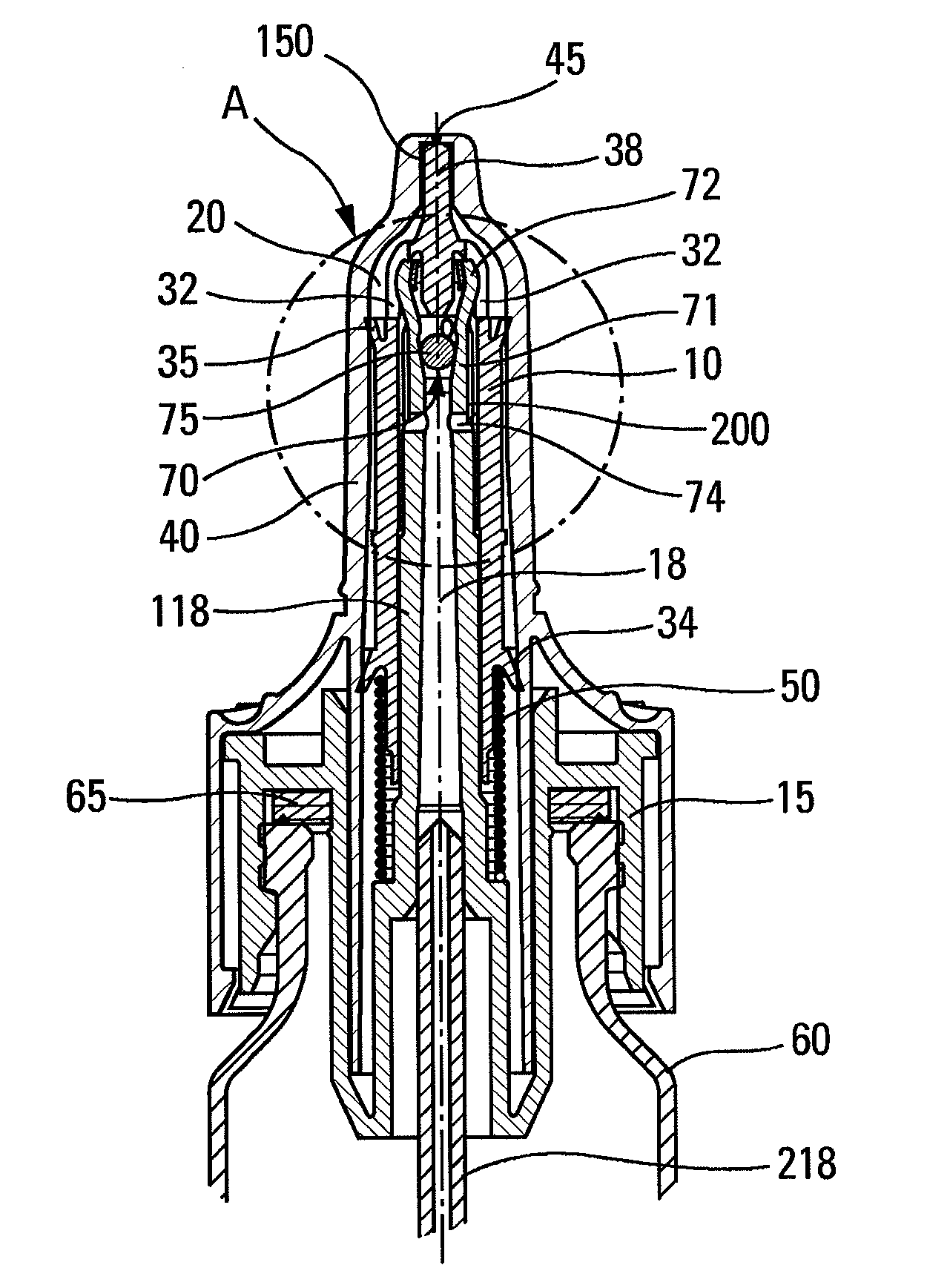
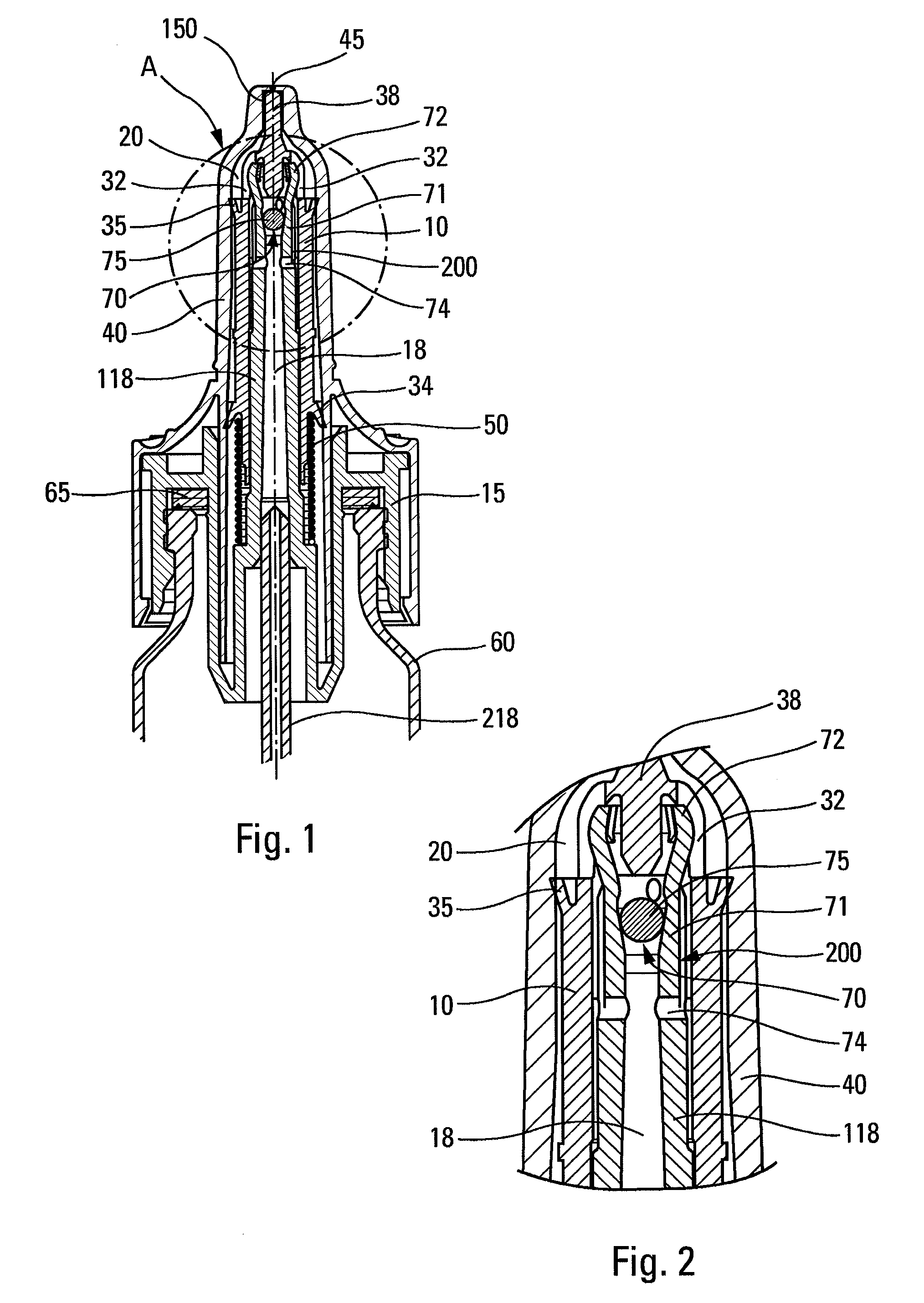
[0031]With reference to the figures, the dispenser pump of the present invention includes a pump body 10 in which at least a first piston 72 slides between a rest position and an actuated position (shown in the figures). The first piston 72 defines, in part, a pump chamber 20, and actuating the pump causes a dose of fluid contained in the pump chamber 20 to be dispensed through a dispenser orifice 45, preferably formed in a dispenser head 40. The pump can advantageously include a plug 38 that is disposed directly upstream from the dispenser orifice 45, and that co-operates with said dispenser orifice by being movable and / or deformable between a closed position of the dispenser orifice 45 and an open position thereof. The pump chamber 20 includes an inlet valve 70 that can be provided in the form of a ball 75 that forms a valve member and that co-operates with a valve seat 71. The valve member 75 is shown in the form of a ball, but it could be provided in some other form. The pump bo...


PUM


Abstract

A fluid dispenser pump having: a pump body; a pump chamber; at least a first piston that slides in the pump chamber between a rest position and an actuated position so as to dispense the fluid; and a dispenser orifice; the pump chamber including an inlet valve that separates the pump chamber from a channel that extends towards a fluid reservoir, a bypass being provided between the channel and the pump chamber, the bypass being disposed upstream from the inlet valve, the bypass connecting the pump chamber to the reservoir when the piston is in its actuated position.

Description

CROSS REFERENCE TO RELATED APPLICATION[0001]This application is a National Stage of International Application No. PCT / FR2007 / 050966 filed Mar. 20, 2007, claiming priority based on French Patent Application No. 0650995, filed Mar. 22, 2006, the contents of all of which are incorporated herein by reference in their entirety.FIELD OF THE INVENTION[0002]The present invention relates to a fluid dispenser pump and to a fluid dispenser device including such a pump.BACKGROUND[0003]Fluid dispenser pumps are well known in the state of the art, in particular for dispensing fluids, liquids, or pastes in the fields of cosmetics, perfumery, or pharmacy. They generally include a piston that slides in a pump body, more particularly in a pump chamber provided in the pump body, and that is adapted to dispense a dose of fluid each time the pump is actuated. The pump chamber generally includes an inlet valve so as to make it possible to define the dose of fluid expelled on each actuation. In addition, ...

Claims


Application Information

Patent Timeline
IPC IPC(8): G01F11/00
CPCB05B11/3004B05B11/3016B05B11/3063B05B11/1004B05B11/1016B05B11/1063
Inventor PRUVOT, SAMUEL
Owner APTAR FRANCE SAS
Why Eureka
Try Eureka