
Enclosure for automated banking machine

Inactive Publication Date: 2010-08-24
DIEBOLD SELF SERVICE SYST DIV OF DIEBOLD NIXDORF INC
View PDF15 Cites 35 Cited by
  • Summary
  • Abstract
  • Description
  • Claims
  • Application Information

AI Technical Summary

Benefits of technology

[0011]It is a further object of an exemplary embodiment to provide an automated banking machine that has an attractive appearance.
[0012]It is a further object of an exemplary embodiment to provide an automated banking machine which is more readily serviced.
[0013]It is a further object of an exemplary embodiment to provide an automated banking machine which is more readily manufactured.
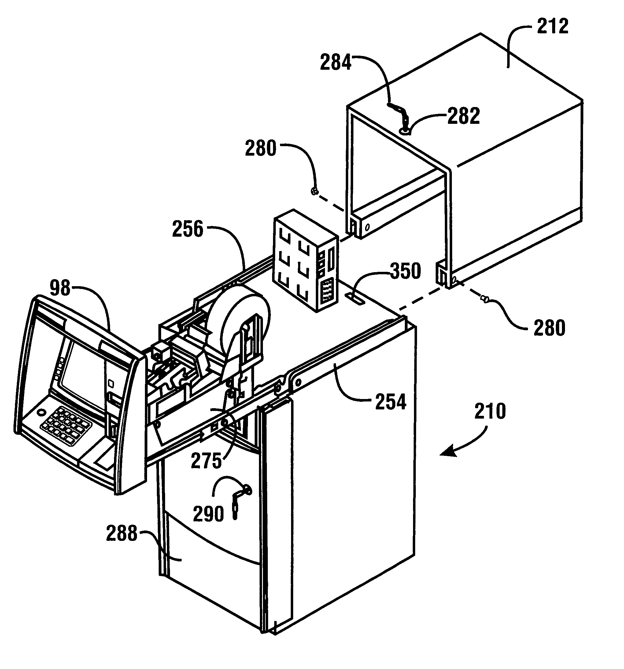
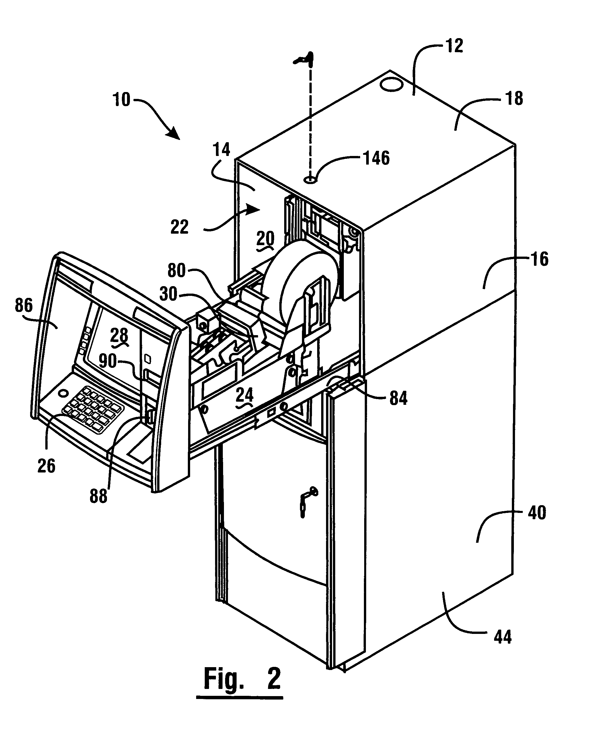
[0020]In one embodiment, a rollout tray is movably mounted in supporting connection with the top housing. Several of the upper banking machine components may be supported on the rollout tray. Additionally, the upper fascia may be mounted to the rollout tray. The rollout tray is movable between a retractable position where the rollout tray is in the interior area and an extended position where the rollout tray extends from the front opening. When the rollout tray is in the retracted position, the upper fascia selectively covers the front opening. When the rollout tray is in the extended position, the banking components mounted thereon may be more readily serviced.
[0027]The above-described embodiments allow ready access to the banking machine components for servicing, as well as simplifying the manufacturing and / or assembly process. The principles described may be applied to numerous ATM configurations.

Problems solved by technology

However, some ATM enclosure designs require that valuable manufacturing time be taken up by the need to align parts and measure gaps in multi-component machines.
However, the efficient use of space can crowd the components making servicing them more difficult.
The manufacture of different ATM chests that are accessed from the front and others that are accessed from the rear adds complexity and cost to manufacturing processes.

Method used


Image

  • Enclosure for automated banking machine
  • Enclosure for automated banking machine
  • Enclosure for automated banking machine

Examples


Embodiment Construction

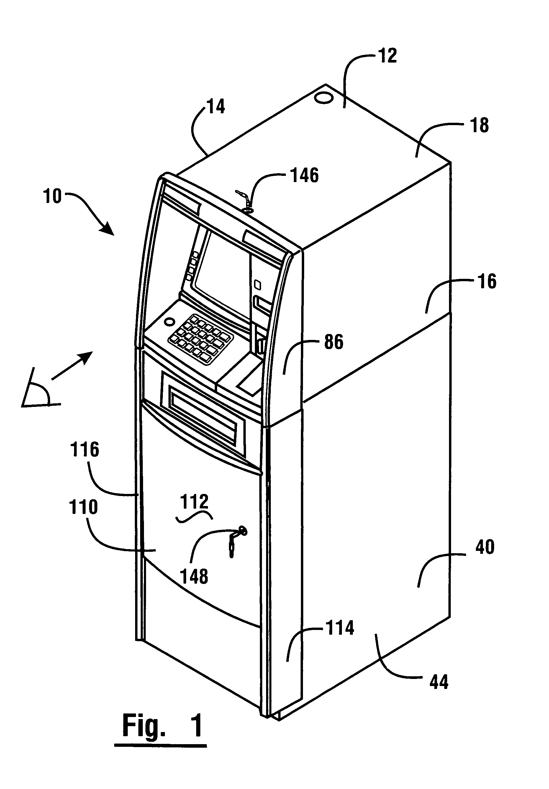
[0045]Referring now to the drawings, and particularly to FIGS. 1-2, there is shown therein an automated banking machine of a first exemplary embodiment, generally indicated 10. In this exemplary embodiment, automated banking machine 10 is an automated transaction machine (ATM). ATM 10 includes a top housing 12 having side walls 14 and 16, and top wall 18. Housing 12 encloses an interior area indicated 20. Housing 12 has a front opening 22. In this exemplary embodiment, the rear of housing 12 is closed by a rear wall 19, shown in FIG. 7. However, in other embodiments, the rear of housing 12 may be accessible through an access door or similar device. Top housing 12 is used to house certain banking machine components such as input and output devices.

[0046]With reference to FIG. 3, in this exemplary embodiment the input devices include a card reader schematically indicated 24. Card reader 24 is operative to read a customer's card which includes information about the customer thereon, su...


PUM


Abstract

An automated banking machine includes a top housing cover slidably mounted with respect to a top wall of the housing of a chest or secure enclosure. The top housing cover includes side channels for slidably receiving spaced upwardly extending flanges mounted on the chest housing. Various upper banking machine components are mounted in supporting connection with the chest housing about the secure enclosure. The components may include a display, a card reader, a receipt printer, a communications device, and a keypad. In an operable condition, the top housing cover is positioned so that a front opening therein is covered by an upper fascia. Removal of one or more fasteners allows the top housing cover to be moved rearwardly to expose the banking machine components for maintenance, replacement or other servicing activity.

Description

TECHNICAL FIELD[0001]This invention relates to automated banking machines. Specifically, this invention relates to automated banking machines having enclosure designs to simplify manufacture and servicing of the banking machines.BACKGROUND ART[0002]Automated banking machines are well known in the prior art. A common type of automated banking machine is an automated teller machine (ATM). Automated banking machines may be used by customers to carry out banking transactions. Common banking transactions include dispensing cash, checking account balances, and transferring funds between accounts. As used herein, automated banking machine refers to any of the types of devices that enable carrying out transactions involving the transfer of funds or value electronically, including but limited to ATMs, cash dispensers, credit card terminals, ticket dispensers, utility payment terminals, smart card value transfer terminals, and devices that perform similar functions.[0003]It is generally valua...

Claims


Application Information

Patent Timeline
IPC IPC(8): G07F19/00
CPCG07F19/20G07F19/205
Inventor LUTE, RICHARD C.UTZ, ZACHARYTULA, PEDROSTEINBACH, KLAUSRAMACHANDRAN, NATARAJANESTEP, MARK
Owner DIEBOLD SELF SERVICE SYST DIV OF DIEBOLD NIXDORF INC
Learn More