Antenna structure for TPMS transmitter

a technology of tire pressure monitoring and antenna structure, which is applied in the direction of antenna details, antenna adaptation in movable bodies, antennas, etc., can solve the problems of low pressure value, easy shortening of short antennas, and easy interference with other electrical components, so as to increase improve radiation efficiency. , the effect of increasing the length of antennas

Active Publication Date: 2010-08-24
APTOS TECH
View PDF4 Cites 0 Cited by
  • Summary
  • Abstract
  • Description
  • Claims
  • Application Information

AI Technical Summary

Benefits of technology

[0009]In order to solve the foregoing problems, one object of the present invention is to provide an antenna structure for a TPMS transmitter. A TPMS transmitter couples with a valve so that a spiral coil within the TPMS transmitter can be electrically connected to a conduct body of the valve to get a specific resonance frequency. Hence, the length of the antenna structure may be increased effectively and the radiation efficiency may be raised.
[0010]One object of the present invention is to provide an antenna structure for a TPMS transmitter. By increasing the length of antenna the radiation efficiency may be enhanced, the power consumption may be lowered, and then the reduction lifetime of battery may further be improved.

Problems solved by technology

After a vehicle has driven for a time or been solarized and been low temperature at night, the vehicle easily produce the leak pressure to cause the pressure value lower the standard.
As far as the driving safe is concerned, the leak pressure has the latent danger especial for high speed to break due to the tire pressure not enough, for example.
In order to avoid the antenna arm excessive long to snap by shaking or solder joint loosing, the antenna can be only designed in short shape; however, the design of short antenna is not only not convenient to fabricate but also easy to be short or interference with other electrical components.
Besides, the weak intensity signal of short antenna easily causes the receiver error erroneous judgment to affect the driving safe.
Moreover, the weak intensity signal needs higher power consumption to enhance the intensity of wireless signal, but that shortens the lifetime of battery.
Therefore, the transmitter of antenna structure has the issue of too big size.

Method used


Image

  • Antenna structure for TPMS transmitter
  • Antenna structure for TPMS transmitter
  • Antenna structure for TPMS transmitter

Examples


Embodiment Construction

[0022]The detailed explanation of the present invention is described as following. The described preferred embodiments are presented for purposes of illustrations and description, and they are not intended to limit the scope of the present invention.

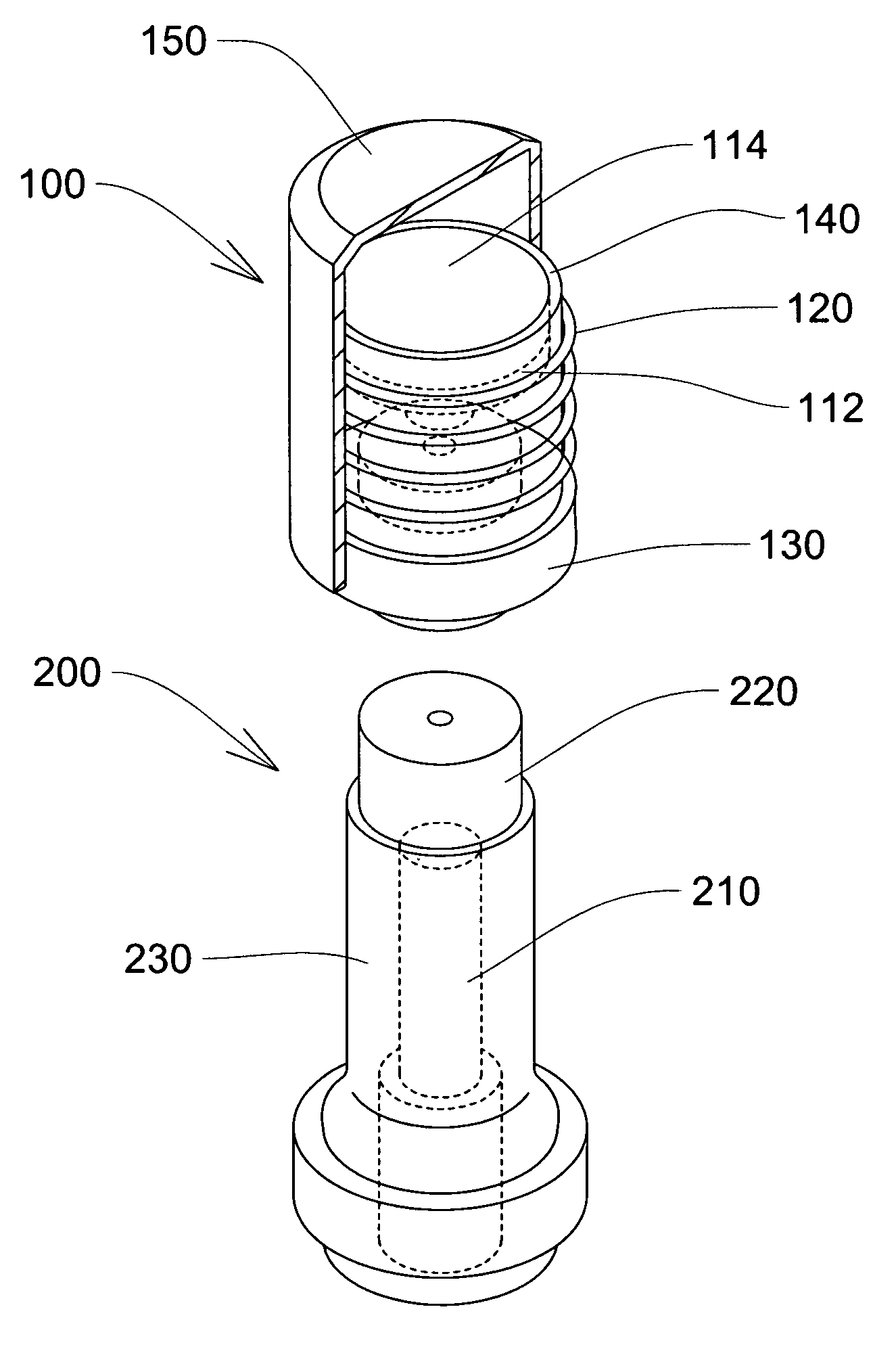
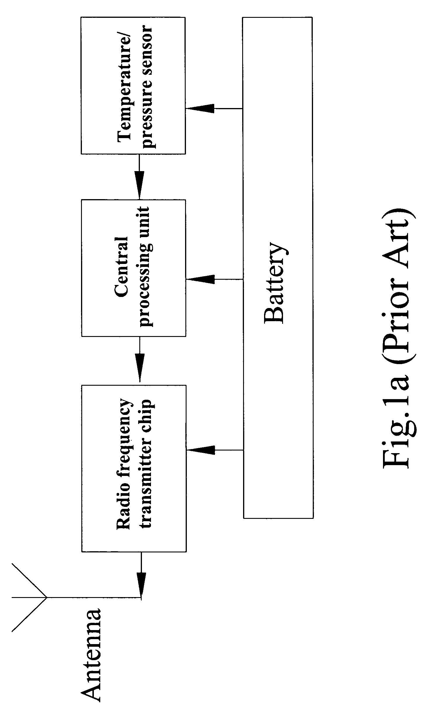
[0023]First, please refer to FIG. 2a and FIG. 2b, the FIG. 2a and FIG. 2b are block diagrams illustrating the TPMS transmitter. As shown in figure, the antenna structure for a TPMS transmitter 100 includes a transmitter module 110 and a spiral coil 120, and the transmitter module 110 and the spiral coil 120 are electrically connected with each other, whereby the spiral coil 120 is electrically connected to a conductive body 210 of a valve 200 by screwing method to form the antenna structure for the TPMS transmitter 160. In one embodiment, the transmitter module 110 includes a first engaged portion(not shown in the diagram), and the first engaged portion is electrically conducted to the spiral coil 120. Besides, the valve 200 further incl...


PUM


Abstract

An antenna structure for a TPMS (Tire pressure Monitoring System) transmitter is disclosed herein. A TPMS transmitter couples with a valve so that a spiral coil within the TPMS transmitter can be electrically connected to a conduct body of the valve to get a specific resonance frequency. Hence, the length of the antenna structure can be increased effectively and the efficacy can be raised.

Description

BACKGROUND OF THE INVENTION[0001]1. Field of the Invention[0002]The present invention relates to an antenna structure for a TPMS (Tire pressure Monitoring System) transmitter to effectively increase the length of antenna and enhance the efficiency.[0003]2. Description of the Prior Art[0004]After a vehicle has driven for a time or been solarized and been low temperature at night, the vehicle easily produce the leak pressure to cause the pressure value lower the standard. As far as the driving safe is concerned, the leak pressure has the latent danger especial for high speed to break due to the tire pressure not enough, for example.[0005]A prior TMPS transmitter includes a transmitter and a receiver set on or around the appearance of bearing to observe the signal form the transmitter set in the tire any time and to understand the pressure and temperature condition of tire. However, as far as the transmitter is concerned, the main types are internal transmitter and external transmitter...

Claims


Application Information

Patent Timeline
Patent Type & Authority Patents(United States)
IPC IPC(8): H01Q1/32
CPCH01Q1/2241
Inventor JOW, EN-MIN
Owner APTOS TECH
Why Eureka
Try Eureka