Silicon composition material for use as battery anode

a composition material and battery technology, applied in the field of composite materials of silicon, can solve the problems of limiting the specific capacity of li-ion batteries, li-si electrodes experiencing a high degree of pulverization and exfoliation during lithiation, and shorter battery life, so as to reduce capacity fading, increase storage capacity per unit weight, and improve the effect of stability

Pending Publication Date: 2022-10-13
LEYDENJAR TECH BV
View PDF0 Cites 0 Cited by
  • Summary
  • Abstract
  • Description
  • Claims
  • Application Information

AI Technical Summary

Benefits of technology

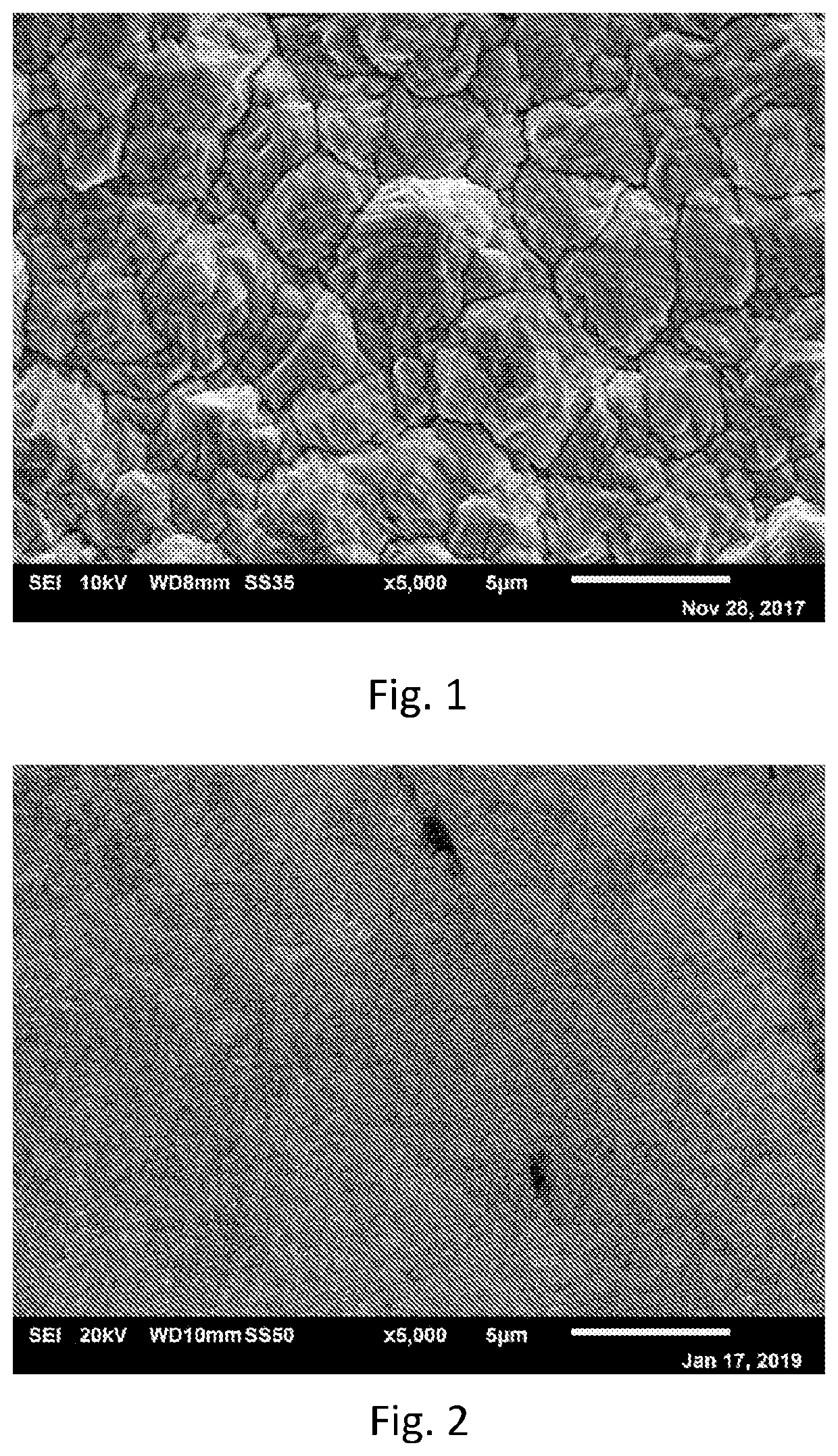
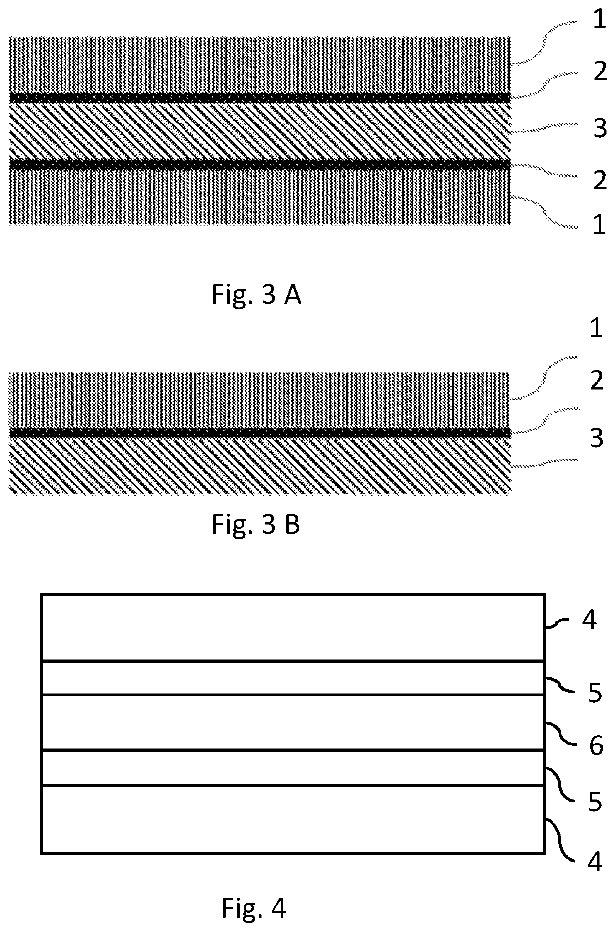
[0011]One of the advantages of the present invention is that the silicon forming process is a self-organizing and spontaneous process for forming on an adhesion layer a continuous amorphous layer nanostructured with a plurality of columns, nanoparticle aggregates, and interfaces there between, yielding a rechargeable battery having an increased storage capacity per unit weight, a reduced capacity fading, and a higher stability in time. The interfaces in the nanostructured amorphous anode layer will locally be perpendicular to the surface of the metal foil that serves as a substrate. The adhesion layer prevents that delamination and / or pulverization of silicon diminishes.
[0059]In a further embodiment, the PECVD process is a microwave PECVD process. To allow for large area production of silicon anode layers, in an advantageous embodiment the microwave plasma is created by an elongated antenna wire, of which each end of the wire is coupled to a microwave generator. The elongated antenna wire provides a substantially linear and uniform field of microwave radiation in the plasma reactor during the formation process, so that a more uniform deposition of the plurality of silicon columns is achieved over a large area. In an embodiment the length of the antenna wire is at least 50 cm, more preferably at least 100, e.g. 120 cm, preferably up to 200 cm, more preferably up to 150 cm. The length of the antenna wire directly influences the surface area produced of the nanostructure silicon thin film layer per unit time. Increasing the length of the antenna wire typically increases the achievable surface area of the nanostructured silicon thin film layer that can be manufactured per unit time.

Problems solved by technology

The relatively low specific capacity of graphite (370 mA h / g) is its main drawback, which limits the specific capacity of Li-ion batteries.
One barrier to full implementation of silicon-based electrodes is the fact that Li—Si electrodes experience a high degree of pulverization and exfoliation during lithiation.
The disintegration of active silicon material will lead to shorter lifetime of the battery and can potentially generate safety issues due to shorting in the battery.
A disadvantage of this method is that manufacturing of the silicon anode material is unattractive as various complex manufacturing steps are required, making the manufacturing process rather expensive.
Also, the scalability to industrial production levels required for commercialization might be difficult.
A disadvantage of these anodes is that these anodes are vulnerable for detachment of silicon from the anode surface.

Method used


Image

  • Silicon composition material for use as battery anode
  • Silicon composition material for use as battery anode
  • Silicon composition material for use as battery anode

Examples


example 1

[0082]The copper foil that gave good adhesion was prepared with an electrodeposition process that also includes electrochemical deposition of a thin ZnO layer (foil 1 in FIG. 10). Next to that a copper foil with a deposited Cr2O3 coating also prepared with electrodeposition (foil 2 in FIG. 10) and a copper foil with a Al-doped ZnO coating deposited by sputtering on top of a thin Cr2O3 layer deposited with electrodeposition (foil 3 in FIG. 10) was prepared. The elemental compositions of the copper foil surfaces was measured using X-ray photoelectron spectroscopy. The results of the measurements given in table 1 show that the surface of the copper foil is covered with a layer of metal oxide, being ZnO, Cr2O3 or Al-doped ZnO.

TABLE 1Elemental composition of the surface of the prepared anode,measured with X-ray photoelectron spectroscopy.ElementCuAlZnCrCOPSClNPeak2 p2 s2 p2 p1 s1 s2 s2 p2 p1 sFoil 12.6017.4020.056.82.20.90.30.1Foil 214.40010.219.055.5000.60.3Foil 30.71.110.82.853.031.500...

example 2

[0085]The cycling stability of electrodes produced with copper foil comprising a zinc oxide adhesion layer are compared to copper foils comprising a coating made of chromate, and a foil that had no adhesion layer. All foils are 8-10 micron thick. Lithium metal was used as counter electrode, which in this example made the silicon-containing copper foils act as the cathode rather than as anode. As these experiments were used for comparison and stability tests, the results can be extrapolated to an electrode layer comprising silicon as anode.

[0086]The electrode that was produced without any adhesion layer was not mechanically stable and could not be used to make a coin cell. Therefore, there are no electrochemical measurements available.

[0087]The electrodes made with copper foils that had chromate and zinc oxides coatings were placed in a coin cell. The electrolyte used comprised LiPF6, with a concentration of 1 M, in a 1:1 by volume mixture of ethylene carbonate and di-ethyl carbonate...


PUM

PropertyMeasurementUnit
thicknessaaaaaaaaaa
thicknessaaaaaaaaaa
porosityaaaaaaaaaa

Abstract

The invention is related to a silicon composite material for use as a rechargeable battery anode, comprising (i) an electrically conductive substrate comprising a foil of copper or titanium, (ii) an adhesion layer attached to the foil comprising at least one or more metals and / or metal compounds and (iii) an electrode layer comprising silicon attached to the adhesion layer.

Description

FIELD OF THE INVENTION[0001]The present invention relates to silicon (Si) composite materials comprising copper (Cu) or titanium (Ti) foils that are useful for anodes in batteries. It furthermore relates to a process of producing silicon composite materials comprising copper or titanium foils. Such anode materials are very useful in batteries as they have a much higher specific capacity than currently used anode materials.BACKGROUND OF THE INVENTION[0002]Energy storage devices, including batteries and capacitors, are used in various applications. Owing to their relatively high energy densities, relatively high specific energy, light weight, and potential long lifetimes, advanced rechargeable batteries are desirable for a wide range of consumer electronics, electric vehicles, grid storage and other important (future) applications. However, despite the increasing commercial prevalence of lithium (Li)-ion batteries, further development of these batteries is needed, particularly for pot...

Claims


Application Information

Patent Timeline
Patent Type & Authority Applications(United States)
IPC IPC(8): H01M4/38H01M4/66H01M4/04
CPCH01M4/386H01M4/661H01M4/667H01M4/0404H01M4/0428H01M2004/021H01M4/134H01M4/1395H01M4/366H01M10/0525H01M2004/028Y02E60/10H01M2004/027
Inventor DIDDEN, ARJEN PETER
Owner LEYDENJAR TECH BV
Why Eureka
Try Eureka