Printing apparatus, printing system, printhead temperature retaining control method

a technology of printhead and temperature control, which is applied in the direction of printing, etc., can solve the problems of increasing power consumption, degrading print quality, and increasing the temperature of ink, so as to reduce the occurrence of ink density unevenness and suppress the increase of power consumption

Inactive Publication Date: 2010-08-24
CANON KK
View PDF17 Cites 9 Cited by
  • Summary
  • Abstract
  • Description
  • Claims
  • Application Information

AI Technical Summary

Benefits of technology

[0021]For example, a printing apparatus, printing system, and printhead temperature retaining control method according to this invention are capable of suppressing an increase in power consumption and reducing ink density unevenness caused by variations in amount of ink discharge upon performing printhead temperature retaining control.
[0025]The invention is particularly advantageous since the maximum temperature which the printhead reaches during printing is predicted and temperature retaining control is executed to adjust the printhead temperature so as to retain the temperature in the printhead at a target temperature determined using the predicted maximum temperature. The invention can, therefore, suppress an increase in power consumption and reduce occurrence of ink density unevenness caused by variations in amount of ink discharge.

Problems solved by technology

However, the heater supplies thermal energy during printing, so the ink temperature continues to rise if the dissipation amount of thermal energy is smaller than its amount of supply.
When an image such as a photograph is printed, density unevenness may appear in the image printed on a print medium, degrading the print quality.
At this time, if the printhead temperature is adjusted to a reference temperature higher than this temperature, a large amount of thermal energy needs to be applied for the temperature adjustment, increasing power consumption.
A relatively long heating time is necessary to heat the printhead substrate to the reference temperature.
As a result, the throughput of the printing apparatus decreases.
Nevertheless, to raise the reference temperature, a large amount of thermal energy must be applied.
When a document or image is so printed as to keep constant at low temperature the maximum temperature the printhead reaches during printing, as described above, a large amount of thermal energy is wastefully applied.
However, when print data such as a text requiring a small number of heater driving counts is used even in high-speed printing, the maximum printhead temperature remains at low level.
Thus, a large amount of thermal energy is applied for a long time in order to keep the printhead temperature high.
However, when a high-quality image like a photographic image is printed, the maximum temperature the printhead reaches during printing may exceed the retained printhead temperature, and the amount of ink discharge may vary.
This results in wastefully consuming power.
However, a large amount of thermal energy is wastefully applied, increasing power consumption.
If temperature retaining control is executed based on a reference temperature lower than the maximum temperature which the printhead actually reaches, the printhead temperature greatly varies, and ink density unevenness appears in an output image.

Method used


Image

  • Printing apparatus, printing system, printhead temperature retaining control method
  • Printing apparatus, printing system, printhead temperature retaining control method
  • Printing apparatus, printing system, printhead temperature retaining control method

Examples


first embodiment

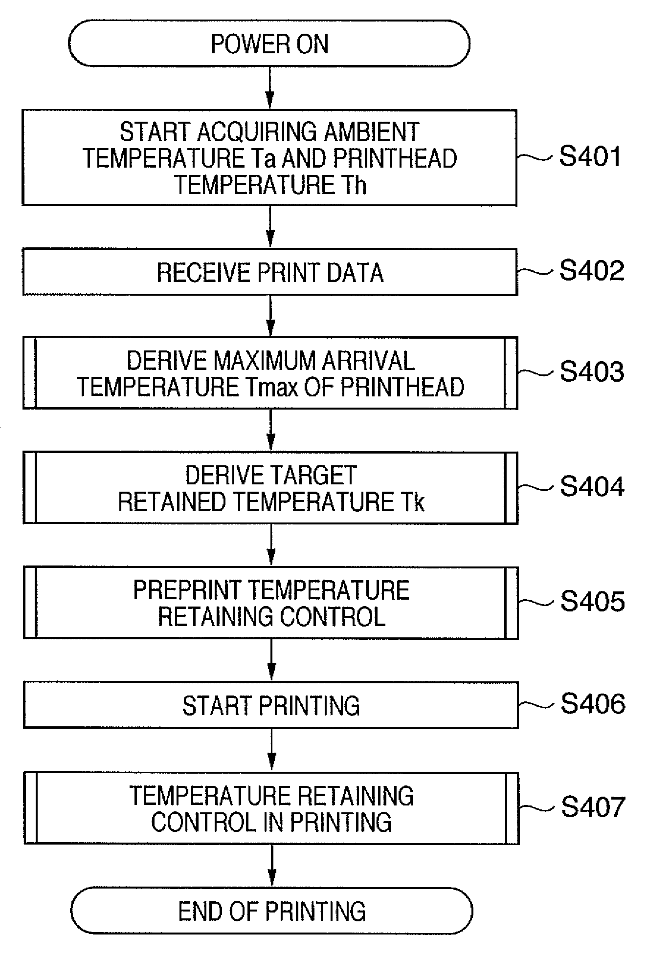
[0064]FIG. 4 is a flowchart showing an outline of a printhead temperature retaining control method according to the first embodiment.

[0065]When the printing apparatus is turned on, an ambient temperature Ta of a printing apparatus and a printhead temperature Th are acquired in step S401. In step S402, print data is received from an external device (host). Then, the process proceeds to step S403 to simulate the transition of the printhead temperature in actual printing from the received data and derive a maximum arrival temperature Tmax at that time.

[0066]In step S404, a target retained temperature Tk at which the printhead temperature is retained is determined in accordance with the maximum arrival temperature Tmax derived in step S403. In step S405, preprint temperature retaining control starts. If the printhead temperature reaches the target retained temperature, the process proceeds to step S406 to start printing. In step S407, printing is performed while temperature retaining co...

second embodiment

[0093]In the first embodiment, information on the print scanning count, the print time per print scanning, and the heater driving count per unit time for each print scanning is derived from print data, obtaining the maximum arrival temperature of the printhead. However, this control requires complicated calculation. Since the calculation is required to complete before the start of printing, this may decrease the throughput of the printing apparatus. In the first embodiment, since all print data are received before the start of printing, the data transfer time becomes long unless a large-capacity buffer is provided. To prevent a decrease in the throughput of the printing apparatus, a large-capacity memory is necessary, raising the cost of the printing apparatus.

[0094]Considering this, the second embodiment will describe a temperature retaining control method which can be performed without requiring any complicated calculation, unlike the first embodiment.

[0095]FIG. 10 is a flowchart ...


PUM


Abstract

The apparatus and method can suppress an increase in power consumption and reduce ink density unevenness caused by variations in the amount of ink discharge upon performing printhead temperature retaining control. The printing apparatus, which prints on a print medium by scanning a printhead having a printing element for generating thermal energy, includes a determination unit which predicts a maximum temperature which the printhead reaches in printing, and determines a target temperature based on the predicted maximum temperature, and an adjustment unit which adjusts the temperature of the printhead in printing on the basis of the target temperature.

Description

BACKGROUND OF THE INVENTION[0001]1. Field of the Invention[0002]The present invention relates to a printing apparatus, printing system, and printhead temperature retaining control method. Particularly, the present invention relates to a printing apparatus which prints an image on a print medium by discharging ink using a printhead, a printing system including the printing apparatus, and a temperature retaining control method for the printhead.[0003]2. Description of the Related Art[0004]These days, performance demand is growing for printing apparatuses used as a printer, copying machine, and facsimile machine. The printing apparatus is required to print high-resolution images like a silver halide photograph, in addition to high-speed printing and full-color printing. To meet these demands, an inkjet printing apparatus can discharge small ink droplets at high frequency. The inkjet printing apparatus is superior to printing apparatuses using other printing methods in terms of high-spe...

Claims


Application Information

Patent Timeline
Patent Type & Authority Patents(United States)
IPC IPC(8): B41J2/00
CPCB41J2/04515B41J2/0454B41J2/04541B41J2/04553B41J2/04563B41J2/0458
Inventor TANAKA, HIROKAZUKANDA, HIDEHIKOSAKAMOTO, ATSUSHIMORIYAMA, JIRO
Owner CANON KK
Why Eureka
Try Eureka