Low power rf control system

a control system and low power technology, applied in power management, transmission systems, transmission, etc., can solve the problems of inability to fully discharge the battery, inability to accept the delay, and inability to rapidly drain the battery, so as to improve the receiver performance, the receiver is more delayed in rendering the operation, and the charge time is mor

Inactive Publication Date: 2010-08-24
SOMFY SAS
View PDF27 Cites 13 Cited by
  • Summary
  • Abstract
  • Description
  • Claims
  • Application Information

AI Technical Summary

Benefits of technology

[0005]A radio-frequency (rf) control system for a component such as but not limited to window coverings, awnings, skylight covers, and screens, includes a remote control device that is manipulable by a user to transmit a wireless rf signal. An rf receiver is associated with the component and is configured for processing the rf signal. Also, a controller is associated with the component for controlling the receiver. The controller saves power by only periodically energizing the receiver. In one embodiment, the remote transmits a series of preamble pulses prior to transmitting a command signal. In this embodiment, the controller causes the receiver to be energized for a first energized period, then to deenergize for a short period if no preamble signal is detected, then to energize for a second energized period, and then to deenergize, if no preamble signal is detected, for long period longer than the short period, prior to once again reenergizing the receiver.
[0010]If desired, at least one bypass capacitor can be electrically connected to the receiver and to ground. As recognized herein, the time to charge a receiver's bypass capacitors varies with capacitance, with larger capacitors yielding better receiver performance once charged but requiring more time to charge and, hence, more delay in rendering the receiver operational. Accordingly, in a preferred embodiment the bypass capacitor can have a capacitance of below five hundred picoFarads (500 pF). Plural bypass capacitors may be provided with at least one having a capacitance not substantially more than one hundred picoFarads (100 pF). We have found that these small capacitances permit faster receiver response time without unduly reducing receiver performance.
[0011]Further, some embodiments may use a surface acoustic wave (SAW) resonator circuit to establish an intermediate frequency (IF) oscillator for the receiver. An LC filter can be associated with the receiver for filtering an IF signal, when a SAW resonator is used. Also, the component can be powered by at least one battery, and the system can include a DC-DC down converter electrically interposed between the battery and receiver to provide a voltage to the receiver with a significant reduction in battery drain at minimal power loss.
[0016]In another aspect, a radio-frequency (rf) control system for a component includes a remote control device manipulable by a user to transmit a wireless rf signal, and an rf receiver associated with the component and configured for processing the rf signal. A controller controls the receiver. The controller adaptively adjusts a noise threshold above which a carrier must be detected to indicate the presence of a control signal. The present invention understands that this feature reduces the amount of time that the receiver undesirably is energized in response to noise rather than desired signals from the transmitter.

Problems solved by technology

As a result, if the receiver is powered by a direct current power source such as a battery it can quickly drain the battery.
On the other hand, continuously pulsing the receiver between power on and power off can help increase battery life, but the battery still can relatively quickly lose power, since the duty cycle between “off” and “on” must be relatively short, to avoid missing a user signal.
Even then, unacceptable delay can exist from when a user toggles a control button on the remote and the window covering starts to move.

Method used


Image

  • Low power rf control system
  • Low power rf control system
  • Low power rf control system

Examples


Embodiment Construction

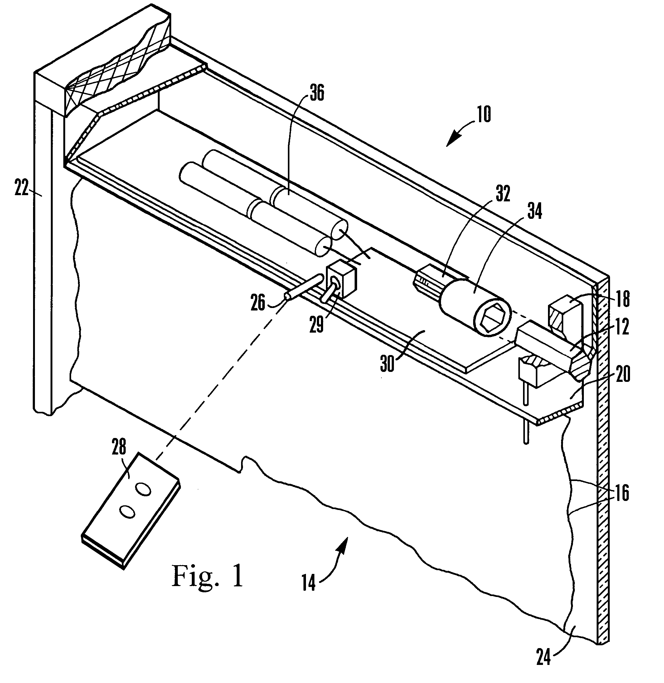
[0024]Referring initially to FIG. 1, for illustration purposes a motorized window covering is shown, generally designated 10, that includes an actuator such as a rotatable rod 12 of a window covering 14, such as but not limited to a shade assembly having raisable (by rolling up) and lowerable (by rolling down, or unrolling) shade 16. As shown, the tilt rod 12 is rotatably mounted by means of a block 18 in a head rail 20 of the window covering 14. In some embodiments the tilt rod 12 is a tube.

[0025]While a roll-up shade is shown as but one non-limiting example of an application of the present low power rf control system, it is to be understood that the rf control system disclosed herein can be used in a wide range of other applications to control devices sought to be controlled. For example, the invention applies to raisable and lowerable pleated shades and cellular shades such as those commonly marketed under the trade names “Silhouette”, “Shangri-La”, etc. as well as to projector s...


PUM


Abstract

A low power rf control system includes a controller that operates at a low clock speed when an associated rf receiver is deenergized and a high clock speed when the controller energizes the receiver. The receiver can be on for a short period, off for a short period if no preamble pulses from a remote control device are received, on for a short period, and then off for a longer period until the next cycle. The receiver remains on to process a command signal when a preamble signal is detected. A DC-DC down converter can be used as a power supply for the receiver, and a SAW resonant circuit can be used as an IF oscillator for the receiver. An LC filter can be associated with the receiver for filtering the IF signal.

Description

I. FIELD OF THE INVENTION[0001]The present invention relates generally to radio-frequency (rf) control systems for controlling such things as window coverings, awnings, security screens, projection screens, lighting systems and controls, battery operated radios, televisions, and stereos, and the like.II. BACKGROUND[0002]Window coverings that can be opened and closed are used in a vast number of business buildings and dwellings. Examples of such coverings include horizontal blinds, vertical blinds, pleated shades, roll-up shades, and cellular shades made by, e.g., Spring Industries®, Hunter-Douglas®, Levellor®, and Somfy®. It is to be understood that while the remote control of window coverings is envisioned and used as one exemplary application, the principles set forth herein may be applied to other systems, including, without limitation, awnings, security screens, projection screens, lighting systems and controls, battery operated radios, televisions, and stereos, and the like whe...

Claims


Application Information

Patent Timeline
Patent Type & Authority Patents(United States)
IPC IPC(8): H04B1/16G08C17/02
CPCG08C17/02H04W52/029E06B9/68Y02D30/70
Inventor WALKER, WINSTON GLENNSAAR, DAVID A.
Owner SOMFY SAS
Why Eureka
Try Eureka