Device for covering a danger area on a roll changer and a method for controlling a device

a technology of danger area and roll changer, which is applied in the direction of curtain suspension device, curtain accessories, building components, etc., can solve the problems of inability to avoid danger, inability to damage other machinery, so as to reduce avoid greater harm, the cost of the device can be kept low, and the effect of reducing the speed of the machin

Inactive Publication Date: 2010-08-31
KOENIG & BAUER AG
View PDF21 Cites 6 Cited by
  • Summary
  • Abstract
  • Description
  • Claims
  • Application Information

AI Technical Summary

Benefits of technology

[0011]The benefits to be achieved in accordance with the present invention consist especially in that a simple mechanical security system protects operating personnel from core parts that could possibly be thrown out of the roll changer in the case of a core burst. The security system of the present invention does not impede the view of a press operator into the roll changer. The ability of the press operator to intervene when a danger is identified, in order to potentially avoid greater harm by stopping the machine early or by reducing the speed of the machine, is preserved.
[0012]By using a roller grid as a protective cover, the costs of the device can be kept low, because existing and economical roller grid structures can be used. Roller grids, which are generally known, consist, for example, of metal profiled pieces, which are capable of withstanding high forces but which have a low weight. The use of such a roller grid also makes it possible to rapidly open and close the protective cover. Furthermore, roller grids can be rolled up into a small space, so that the dimensions of the roll changer to be secured are not excessively increased.

Problems solved by technology

In such an occurrence, flying core pieces can injure operating personnel or can damage other machinery.
This danger exists especially above a paper web width of greater than approximately 2,000 mm, a web speed especially of more than 10 m / s, and particularly above a cardboard core diameter of approximately 76 mm.
With the traditional zone safety systems, the dangers associated with such bursting cores cannot be averted.
Such persons would not be able to avoid the core parts that would be torn out of the holder at high speed.

Method used


Image

  • Device for covering a danger area on a roll changer and a method for controlling a device
  • Device for covering a danger area on a roll changer and a method for controlling a device
  • Device for covering a danger area on a roll changer and a method for controlling a device

Examples


Embodiment Construction

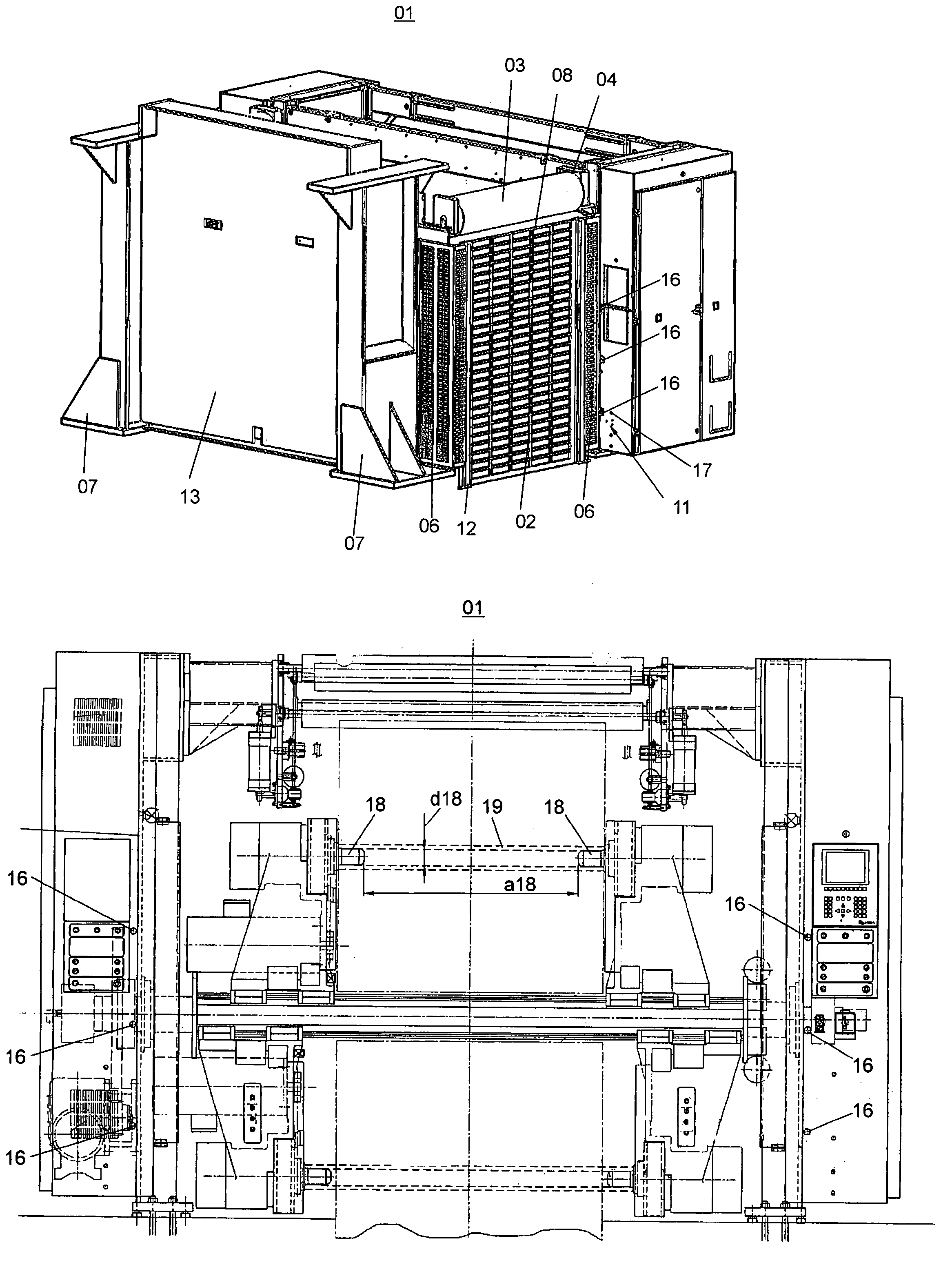
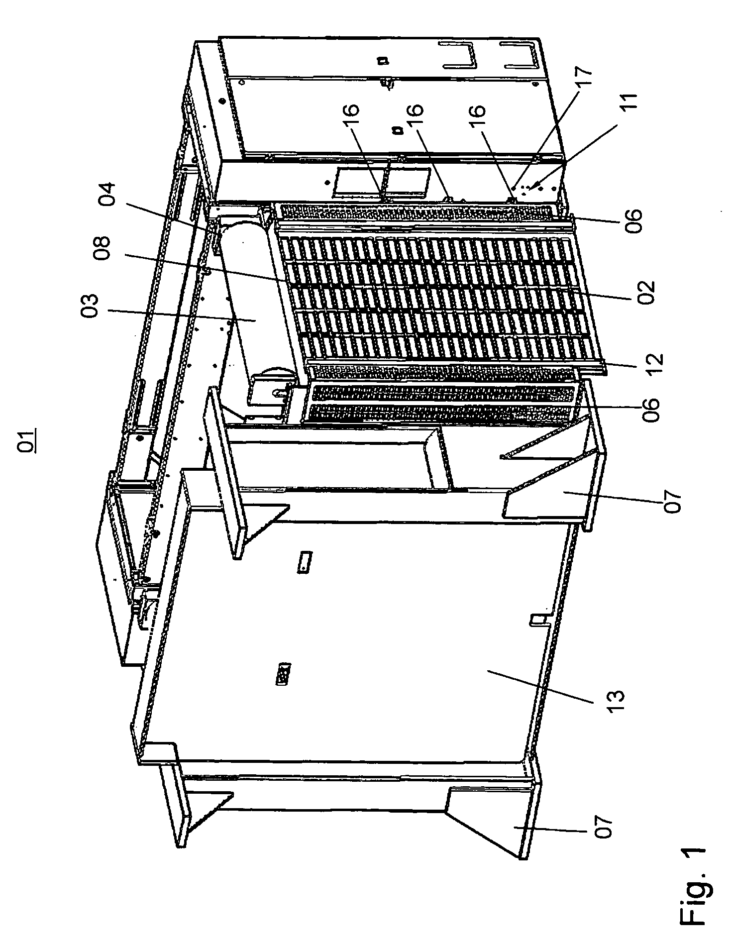
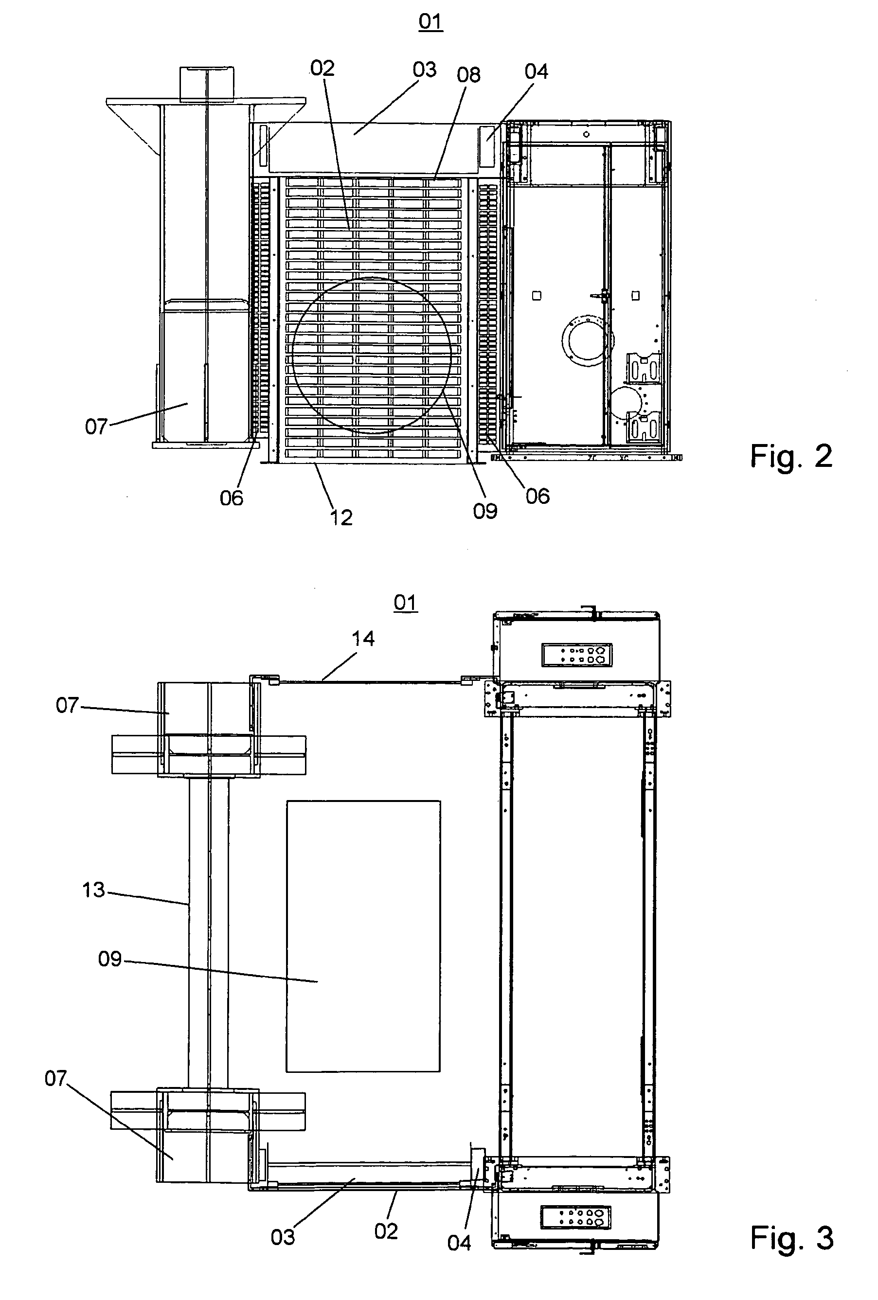
[0021]FIG. 1 shows a perspective view of a roll changer 01 with a device, which is preferably configured as a protective cover 02, such as, for example, a roller grid 02. In the discussion which follows, a method for controlling the device will also be specified within the context of this depiction shown in FIG. 1.

[0022]The roller grid 02 can be rolled up onto a grid roll 03, which grid roll 03 can be actuated in two rotational directions via a roll drive 04. The roller grid 02 is connected via grid guides or grid guards 06, or by other connecting elements, to the roll changer 01 on a first side of the roller grid 02 and to a support 07 on the other side of the roller grid 02. Suitable roller grids 02 are preferably arranged at all access points or feed openings to the roll changer 01, so that personnel cannot enter the danger zone, in which danger zone parts of a broken core could be thrown around in the case of a core burst.

[0023]The protective cover 02 can also be configured, for...


PUM


Abstract

A device is provided for use in covering a danger area on a roll changer that can carry at least one roll of material to be directed to a rotary, web-fed printing press. A cover is provided with a drive that can move the cover. A control unit is provided to control the drive for the cover. The cover is closed in a first operational state and is open in a second operational state. The roll of material, that is supported by the roll changer, has a first rotational speed or web speed when the cover is in the first, closed operational state. In the second, cover opened, operational state, the roll of material also has a second rotational or web speed which is greater than zero. A method for controlling a device on a roll changer is also disclosed.

Description

CROSS-REFERENCE TO RELATED APPLICATIONS[0001]This application is the U.S. national phase, under 35 USC 371, of PCT / EP2006 / 067227, filed Oct. 10, 2006; published as WO 2007 / 096007 A1 on Aug. 30, 2007, and claiming priority to DE 10 2006 008 104.8, filed Feb. 20, 2006, the disclosures of which are expressly incorporated herein by reference.FIELD OF THE INVENTION[0002]The present invention is directed to a device for covering a danger area on a roll changer and also to a method for controlling such a device. The roll changer supports at least one material roll and has a protective cover. A drive is provided to move the protective cover. A control unit is used to control the drive for the protective cover.BACKGROUND OF THE INVENTION[0003]A process of providing a zone safety system to ensure operational safety in the area around large moved material rolls is known from WO 2005 / 080241 A2. To accomplish this process, an installation of fencing around the perimeter of a material roll wareho...

Claims


Application Information

Patent Timeline
Patent Type & Authority Patents(United States)
IPC IPC(8): B65H19/00
CPCB65H19/00B65H26/00B65H2553/30
Inventor HEIMRICH, BERND RUDOLFKELLER, MARTIN RICHARDRITTER, WALTERVORWERK, FRANZ JOSEF
Owner KOENIG & BAUER AG
Why Eureka
Try Eureka