Independent wheel suspension for the rear wheels of motor vehicles

a technology for rear wheels and motor vehicles, applied in the direction of suspension arms, resilient suspensions, vehicle components, etc., to achieve the effect of preventing undesirable joint steering of the wheel, less bent at an angle, and favorable tying

Active Publication Date: 2010-08-31
AUDI AG
View PDF25 Cites 32 Cited by
  • Summary
  • Abstract
  • Description
  • Claims
  • Application Information

AI Technical Summary

Benefits of technology

[0004]It is proposed, in accordance with the invention that, with the wheel suspension viewed from the top, in essence the other guide rod acting as track rod in particular in the lower guide rod plane is inclined from the outside inward so that the point of intersection of imaginary extension of the other guide rod and the rear bearing points of the lower guide rod or trapezoidal guide rod is positioned beyond the extended axis of the center of the wheel. This configuration first of all yields advantageous intrinsic steering behavior of the wheel suspension in the presence of longitudinal forces acting on the wheel (in a braking process, for example) and in the presence of lateral forces (acting on the outer wheel during travel on a curve)

Problems solved by technology

The position of the other guide rod in the lower guide rod plane results in uncoupling of toe-in and camber of the wheel

Method used


Image

  • Independent wheel suspension for the rear wheels of motor vehicles
  • Independent wheel suspension for the rear wheels of motor vehicles
  • Independent wheel suspension for the rear wheels of motor vehicles

Examples


Embodiment Construction

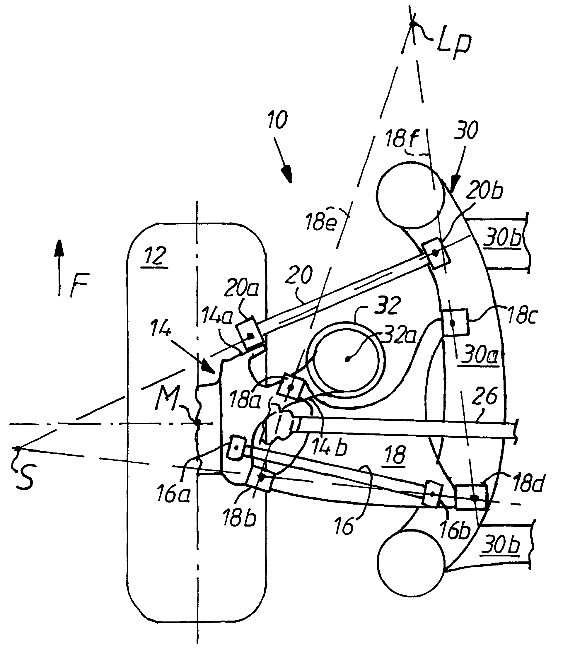
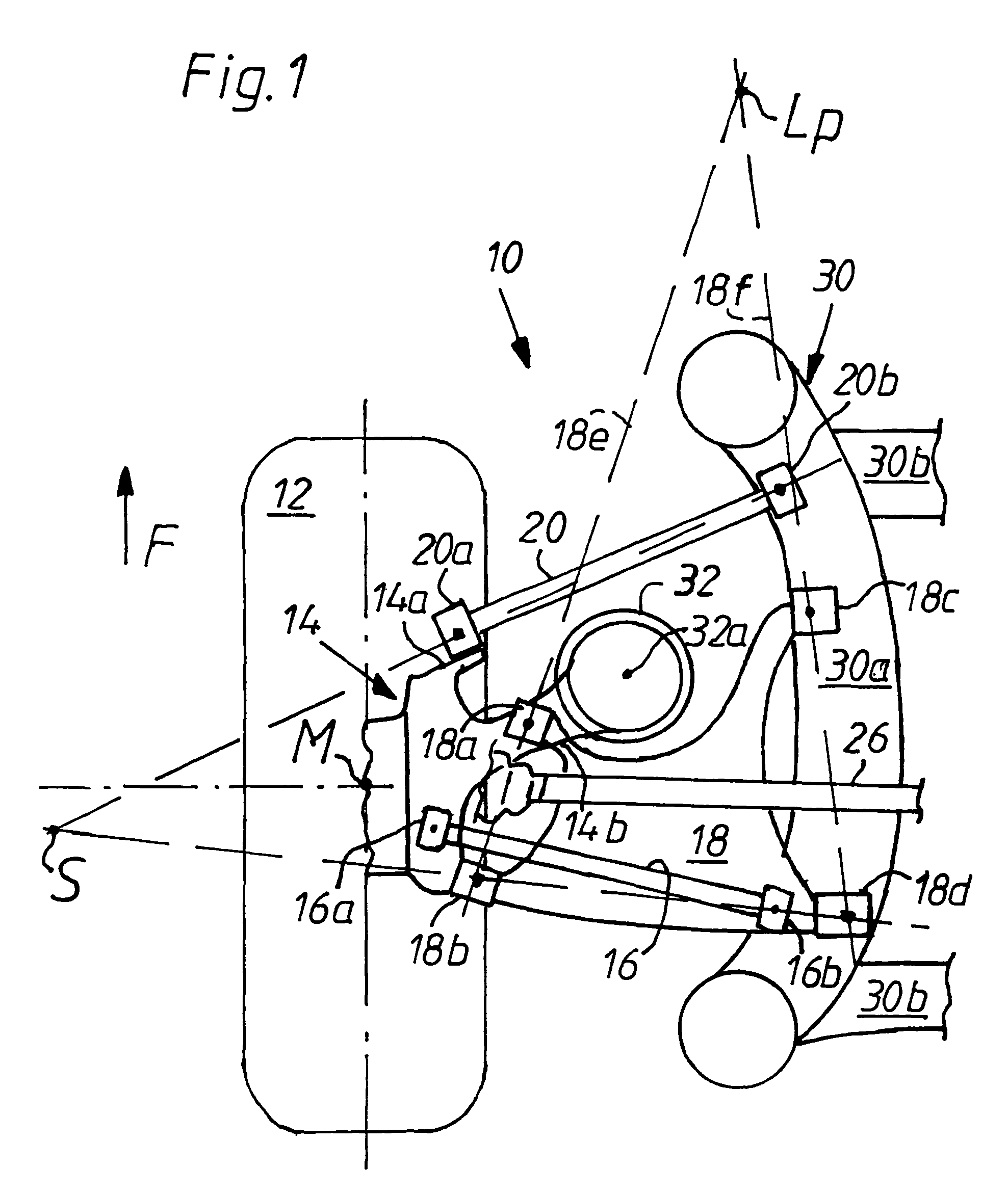
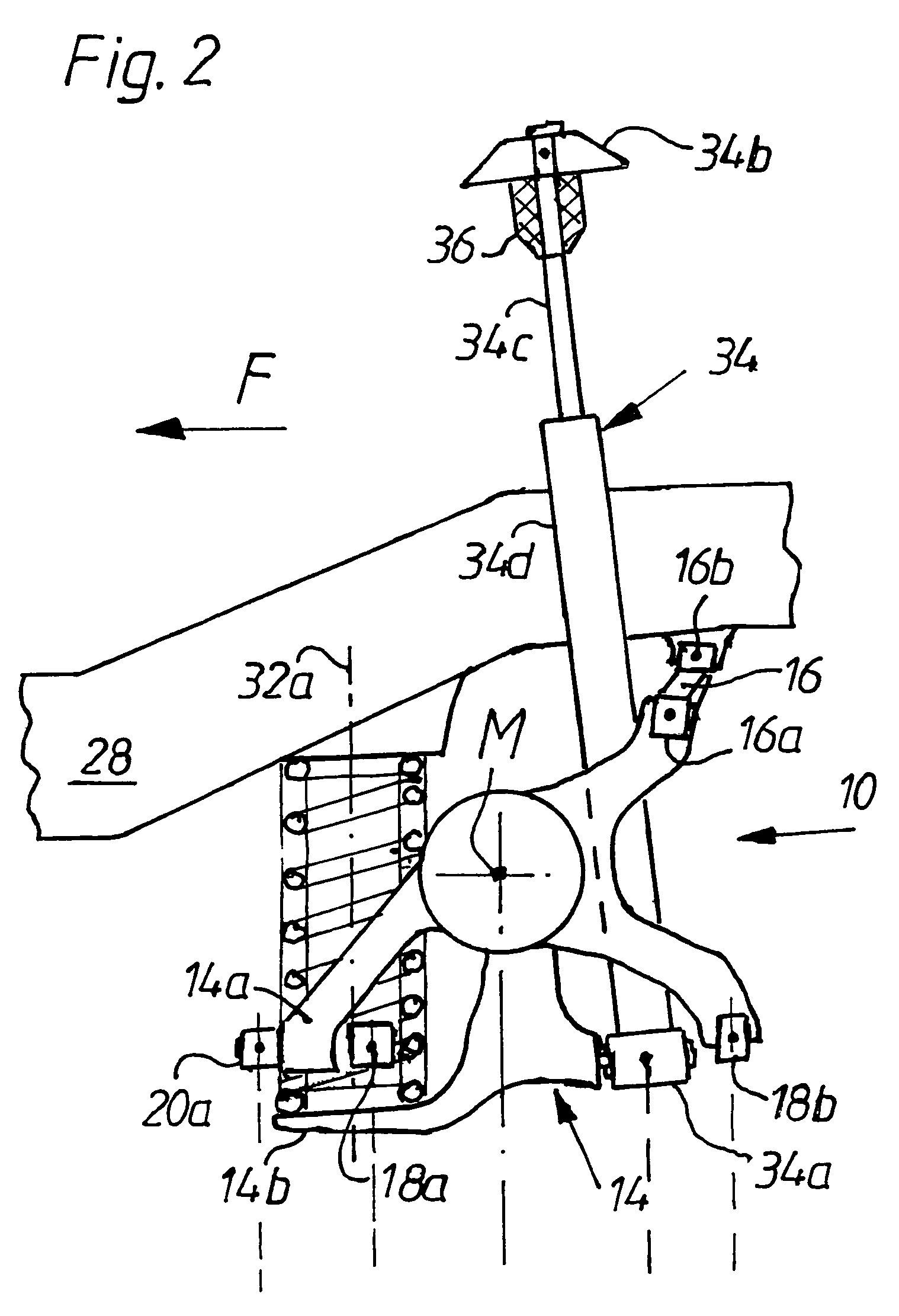
[0021]The wheel support 14—in which the rear wheel 12 is rotatably mounted above a drive shaft 26 not shown—is guided in an upper guide rod plane (see FIG. 2) over the guide rod 16 with guide rod bearings 16a, 16b and in a lower guide rod plane by means of the guide rod 18 by way of guide rod bearings 18a, 18b and 18c, 18d, and, lastly, over the other guide rod 20 by way of guide rod bearings 20 by way of guide rod bearings 20a, 20b as a guide.

[0022]The guide rod bearings 16a, 18a, 18b, 20a are mounted, in a manner yet to be described, on the wheel support 14 on one side and on the body of the vehicle or in the exemplary embodiment (shown only in part) on an auxiliary frame 30 on the other side by conventional means to form drag bearings. The guide rod bearings in question could be conventional rubber-metal bush bearings and optionally in part ball bearings. The auxiliary frame 30 has on each side of the vehicle a spar 30a and cross-spars 30b connecting them to form a frame, the low...


PUM


Abstract

The invention relates to an independent wheel suspension for the rear wheels of motor vehicles, having a wheel support which is hinge-connected to at least one upper and one lower control arm, the lower control arm being connected by way of two more or less horizontal arm bearings forming pivot axes on the body of the motor vehicle and on the wheel support and a guide arm of the wheel support to another bearing, and also having a bearing spring resting on the wheel support and a more or less vertically oriented telescopic shock absorber. For the creation of a structurally and elastokinematically favorable wheel suspension it is proposed, as viewed from above, that the other guide rod is mounted more or less in the lower guide rod plane and diagonally forward from the exterior toward the interior, in such a way that the intersection of imaginary extensions of the other guide rod and the rear bearing points of the lower guide rod is positioned beyond the extended wheel center axis.

Description

[0001]The invention relates to an independent wheel suspension for the rear wheels of motor vehicles.BACKGROUND OF THE INVENTION[0002]A wheel suspension such as this is disclosed, for example, by EP 0 288 654 131, and is also designated a trapezoidal guide rod shaft. The bearing spring, not shown, and the telescopic shock absorber generally rest on the wheel support and / or on the lower connecting or trapezoidal guide rod. In addition, the lower trapezoidal guide rod is connected to the wheel support by way of two guide rod bearings the extended pivot axis of which intersects as a tilted shaft the pivot axis of guide rod bearings upstream from the wheel suspension as viewed in the direction of travel of the motor vehicle. In the upper guide rod plane there are also two guide rods hinge-connected to the wheel support, the front guide rod of which, because of its spatial configuration, effects a specific elastokinematic roll steer effect of the wheel suspension with preferred understee...

Claims


Application Information

Patent Timeline
IPC IPC(8): B60G7/00
CPCB60G3/20B60G3/26B60G2200/14B60G2200/18
Inventor SCHMIDT, WALTERMULLER, HUGOBRANDL, HANS JURGENKILLIAN, FRIEDRICH
Owner AUDI AG
Why Eureka
Try Eureka