
Method and apparatus for high frequency component smoothing, and image display apparatus

a high frequency component and image display technology, applied in the field of methods and apparatuses for processing images, can solve problems such as image distortion and bad images, and achieve the effects of reducing moiré, reducing distortion, and reducing images

Inactive Publication Date: 2014-03-18
MITSUBISHI ELECTRIC CORP
View PDF19 Cites 2 Cited by
  • Summary
  • Abstract
  • Description
  • Claims
  • Application Information

AI Technical Summary

Benefits of technology

This solution effectively corrects geometrical image distortions and reduces moiré artifacts in output images, ensuring high-quality image display even during partial magnification or reduction, thereby improving image clarity and reducing unwanted aliasing effects.

Problems solved by technology

A projection display apparatus such as a rear projection TV causes an image distortion resulting from a positional relationship between a screen and a projection light source, or aberration or the like that is generally inherent in any optical system.
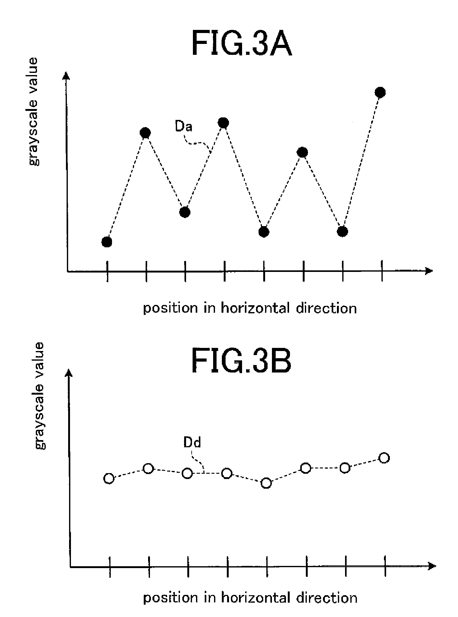
A problem with the conventional technique in the foregoing description, however, is that when image data containing a high frequency (HF) component such as a checkered pattern is supplied, moiré occurs in an output image, owing to aliasing resulting from re-sampling at a pixel position after conversion of an original image, thus leading to very bad-looking images.

Method used


Image

  • Method and apparatus for high frequency component smoothing, and image display apparatus
  • Method and apparatus for high frequency component smoothing, and image display apparatus
  • Method and apparatus for high frequency component smoothing, and image display apparatus

Examples


embodiment 1

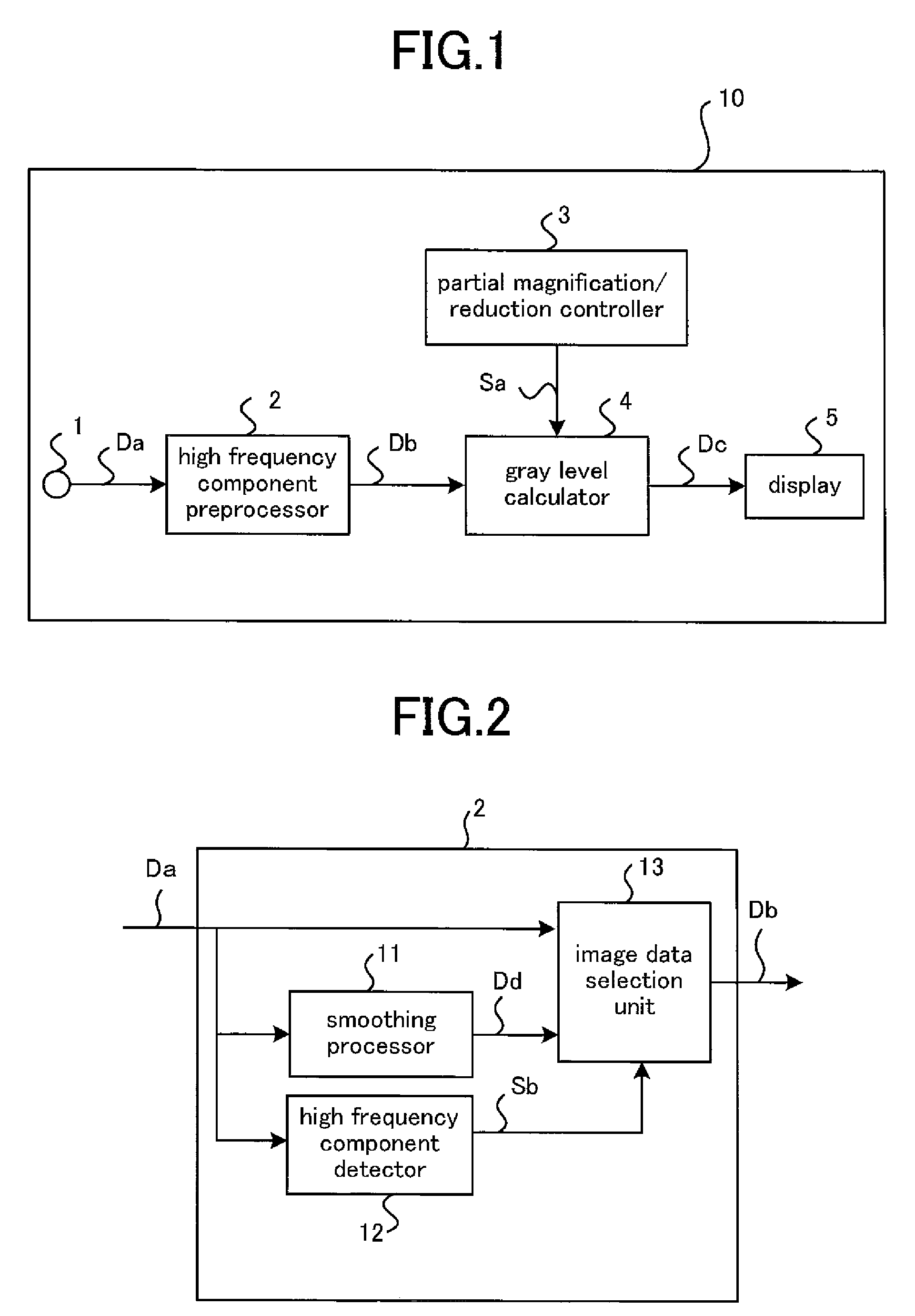
[0027]FIG. 1 is a block diagram showing a general configuration of an image display apparatus 10 according to Embodiment 1 of the present invention.

[0028]The image display apparatus 10 according to Embodiment 1 includes an input terminal 1, a high frequency (HF) component preprocessor 2, a partial magnification / reduction controller 3, a gray level calculator 4, and a display 5.

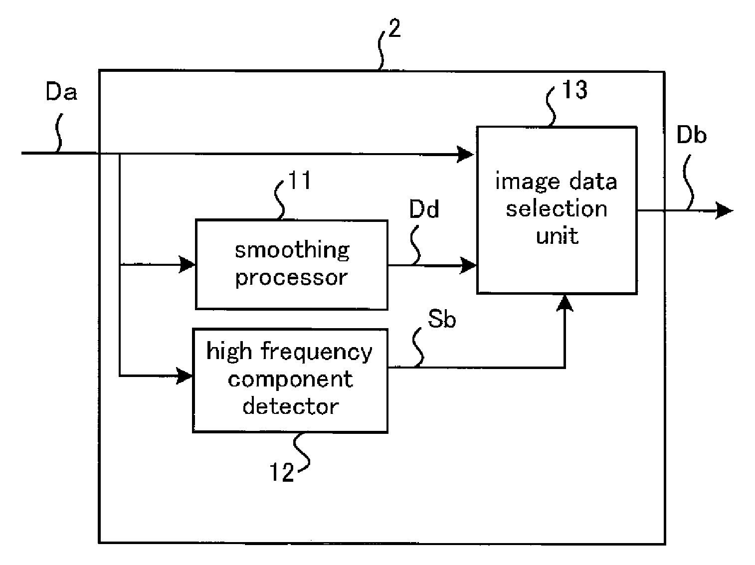
[0029]The input terminal 1 receives input image data Da that in turn is supplied to the HF component preprocessor 2. The preprocessor 2 is a HF-component smoothing processor that smoothes HF components of the input image data Da, to generate and deliver smoothed-HF-component image data Db. The partial magnification / reduction controller 3 delivers to the gray level calculator 4 partial magnification / reduction control information Sa that defines a pixel position obtained after expanding / reducing image data for each area of the data, based on a command of an amount of correction from a controller (not shown). The...

embodiment 2

[0069]While in Embodiment 1 a situation where the HF component preprocessor 2 performs preprocessing using adjacent pixels in the horizontal direction of a pixel of interest has been described, HF component preprocessing may be performed, in addition to adjacent pixels in the horizontal direction, using those in the vertical direction, based on the smoothed-HF-component image data Db to be supplied from the image data selection unit 13. In this case, since the preprocessing using adjacent pixels in the vertical direction differs in terms of reference pixels alone and the rest of processing is similar to that of the selection unit 13 as discussed above, detail description thereof will be omitted. In this manner, after the preprocessing has been performed by using adjacent pixels in the horizontal direction, another preprocessing is done by using those in the vertical direction, whereby a pattern that cannot be detected by only preprocessing in the horizontal direction—for instance, a...


PUM


Abstract

A method and apparatus for processing images, and an image display apparatus are provided that can produce favorable images even when digitized image are partially magnified (enlarged) or reduced (shrunk). The apparatus for expanding or reducing input image data supplied thereto, for each area of the image data, comprises a high frequency (HF) component smoothing processor that generates smoothed-HF-component image data by smoothing HF components of the input image data; a partial magnification / reduction controller that generates partial magnification / reduction control information that designates positions of pixels in image data obtained after expanding or reducing the input image data for each image area; and a pixel data generator that generates pixel data of pixel positions designated by the partial magnification / reduction control information in the smoothed-HF-component image data, by using pixel data in a neighborhood of the designated pixel positions.

Description

FIELD OF THE INVENTION[0001]The present invention relates to methods and apparatuses for processing images, and image display apparatuses, whereby digitized images are partially magnified (enlarged) or reduced (shrunk), to display the images. More particularly, the invention relates to such apparatuses and methods that avoid moiré in an output image occurring when an image having relatively high spatial frequencies is supplied.BACKGROUND OF THE INVENTION[0002]A projection display apparatus such as a rear projection TV causes an image distortion resulting from a positional relationship between a screen and a projection light source, or aberration or the like that is generally inherent in any optical system. To correct the distortion, techniques to project light of an image created by applying an inverse distortion characteristic to the distortion are conventionally known.[0003]As one of the techniques, there is a technique for correcting image data by electrical signal processing; fo...

Claims


Application Information

Patent Timeline
Patent Type & Authority Patents(United States)
IPC IPC(8): G06K9/32
CPCG06T3/4007G09G5/00G09G2320/02
Inventor OKUDA, NORITAKAMORIYA, SHOTAROKUBO, TOSHIAKIYAMANAKA, SATOSHI
Owner MITSUBISHI ELECTRIC CORP
Learn More