Anti-glare and anti-reflection device

a technology of anti-glare and anti-reflection, which is applied in the field of optical devices, can solve the problems of user discomfort, lowered anti-glare effect of anti-glare films, and user's inability to read for a long time, and achieves favorable anti-glare and anti-reflection effects

Active Publication Date: 2019-07-30
AU OPTRONICS CORP
View PDF20 Cites 2 Cited by
  • Summary
  • Abstract
  • Description
  • Claims
  • Application Information

AI Technical Summary

Benefits of technology

[0005]The invention provides an anti-glare and anti-reflection device which provides favorable anti-glare and anti-reflection effects.
[0007]To sum up, in an embodiment of the invention, the thickness of the anti-reflection film is considerably less than a recess depth of the rough surface, and that the anti-reflection film is able to be conformally disposed on the rough surface. As such, the anti-reflection film disposed on the rough surface of the base is less likely to affect diffusion effect of the micro protrusions of the rough surface, and that the anti-glare and anti-reflection device is equipped with favorable anti-glare as well as anti-reflection effects.

Problems solved by technology

Nevertheless, a display panel reflects ambient light easily compared to the conventional paper, and the reflected ambient light may cause discomfort to a user, and consequently, the user may not be able to read for a long period of time.
Nevertheless, an anti-glare film of high haze is generally not disposed on the display surface of the display panel in order to prevent problems such as blurring, white mist, and sparkles from happening.
Even though an anti-reflection film is disposed on the anti-glare film with haze in order to improve the white mist and other problems, anti-glare effect of the anti-glare films is lowered, or expected anti-reflection effect of the anti-reflection film is unable to be provided and / or phenomenons such as color shift occur.

Method used


Image

  • Anti-glare and anti-reflection device
  • Anti-glare and anti-reflection device
  • Anti-glare and anti-reflection device

Examples


Embodiment Construction

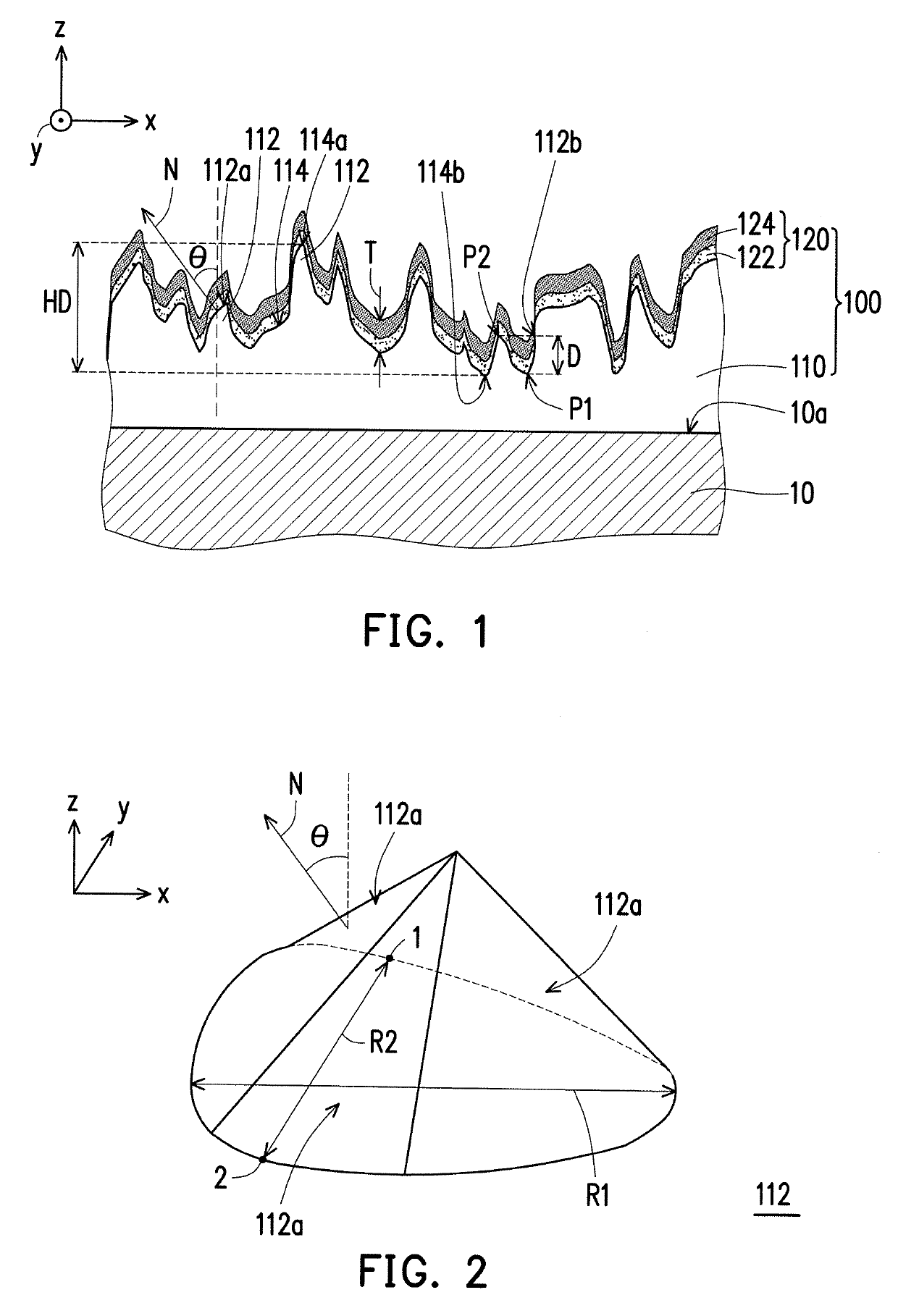
[0018]FIG. 1 is a schematic cross-sectional view of an anti-glare and anti-reflection device according to an embodiment of the invention. Referring to FIG. 1, a display panel 10 has a display surface 10a facing a user. The display surface 10a is located in an area of the display panel 10 which is able to display a screen, i.e., an active area (AA) as called in the art most of the time. An anti-glare and anti-reflection device 100 is configured to be disposed on the display surface 10a, so as to diffuse an ambient light and to reduce an amount of the ambient light being reflected and thus enhance comfortability for a user when viewing the display panel 10. In terms of display media types, in the present embodiment, the display panel 10 may be a liquid crystal display (LCD); nevertheless, the invention is not limited thereto. In the rest of the embodiment, the display panel 10 may also be an organic light emitting diode (OLED), a micro-LED display, or other types of suitable displays....


PUM

PropertyMeasurementUnit
axis length R2aaaaaaaaaa
angleaaaaaaaaaa
distanceaaaaaaaaaa

Abstract

An anti-glare and anti-reflection device including a base and an anti-reflection film is provided. The base includes a plurality of micro protrusions. The micro protrusions are connected to each other to form a rough surface. The rough surface has a first point furthest from a display surface and a second point closest to the display surface. A distance between the first point and the second point in a normal direction of the display surface is HD, and 1 μm≤HD≤20 μm. A normal projection of each of the micro protrusions on the display surface has a first axis length R1 and a second axis length R2, 1 μm≤R1≤20 μm, and 1 μm≤R2≤20 μm. The anti-reflection film is disposed on the rough surface. The anti-reflection film has a thickness T in a normal direction of the rough surface, and T / H≤0.1.

Description

CROSS-REFERENCE TO RELATED APPLICATION[0001]This application claims the priority benefits of Taiwan application serial no. 106121869, filed on Jun. 30, 2017, and Taiwan application serial no. 106131564, filed on Sep. 14, 2017. The entirety of each of the above-mentioned patent applications is hereby incorporated by reference herein and made a part of specification.BACKGROUND OF THE INVENTION1. Field of the Invention[0002]The invention relates to an optical device. More particularly, the invention relates to an anti-glare and anti-reflection device.2. Description of Related Art[0003]Display panels are widely adopted in daily life owing to advantages such as compact sizes, low radiation, and power saving. Along with increasing popularity of the display panels and information explosion, people rely more and more on the display panels, rather than conventional paper, to read information. Nevertheless, a display panel reflects ambient light easily compared to the conventional paper, and ...

Claims


Application Information

Patent Timeline
Patent Type & Authority Patents(United States)
IPC IPC(8): G02B1/11
CPCG02B1/11G02B5/0221G02B5/0284
Inventor TUNG, KUAN-YULIAO, SHU-WENKAO, WANG-SHUO
Owner AU OPTRONICS CORP
Why Eureka
Try Eureka