Oscillating internally meshing planetary gear reducer

a technology of internal meshing and gear reducers, which is applied in the direction of toothed gearings, belts/chains/gearrings, and gearings. it can solve the problems of large diameter of distributing gears, unavoidably becoming large, and complicated shapes, so as to reduce the cost, reduce the speed, and reduce the effect of high speed reduction ratio

Inactive Publication Date: 2010-08-31
SUMITOMO HEAVY IND LTD
View PDF14 Cites 11 Cited by
  • Summary
  • Abstract
  • Description
  • Claims
  • Application Information

AI Technical Summary

Benefits of technology

[0012]The present invention was made in order to solve the above problems at the same time, and aims at providing an oscillating internally meshing type planetary gear reducer capable of realizing a low cost and the high speed reduction ratio.
[0014]According to the above constitution, a speed can be reduced in two stages in which the input gear receives power from the power source and the power is transmitted from the input shaft gear of the input shaft (via the distributing gear) to the eccentric body shaft gear, and a high speed reduction ratio can be realized. Additionally, in this case, it is unnecessary to make a diameter of the distributing gear large and to make a shape thereof complicated, and thus a cost can be reduced.
[0015]Additionally, a diameter of the input gear is made larger than that of the pinion and a diameter of the eccentric body shaft gear is made larger than that of the input shaft gear, and thus the high (large) speed reduction rate can be obtained.
[0016]There can be provided an oscillating internally meshing planetary gear reducer capable of realizing a low cost and a high speed reduction ratio.

Problems solved by technology

The pinion 14 directly meshes with the distributing gear 26 of which an axis is largely gapped from that of the pinion 14, and thus a diameter of the distributing gear 26 unavoidably becomes large and a shape thereof becomes complicated, and there arises a problem in terms of cost.
However, since the three eccentric body shafts 30 do not rotate at the same time, there arises a gap due to backlash which is not preferable in terms of precision.

Method used


Image

  • Oscillating internally meshing planetary gear reducer
  • Oscillating internally meshing planetary gear reducer
  • Oscillating internally meshing planetary gear reducer

Examples


Embodiment Construction

[0025]An example of embodiments of the present invention will be described in detail with reference to the accompanying drawings.

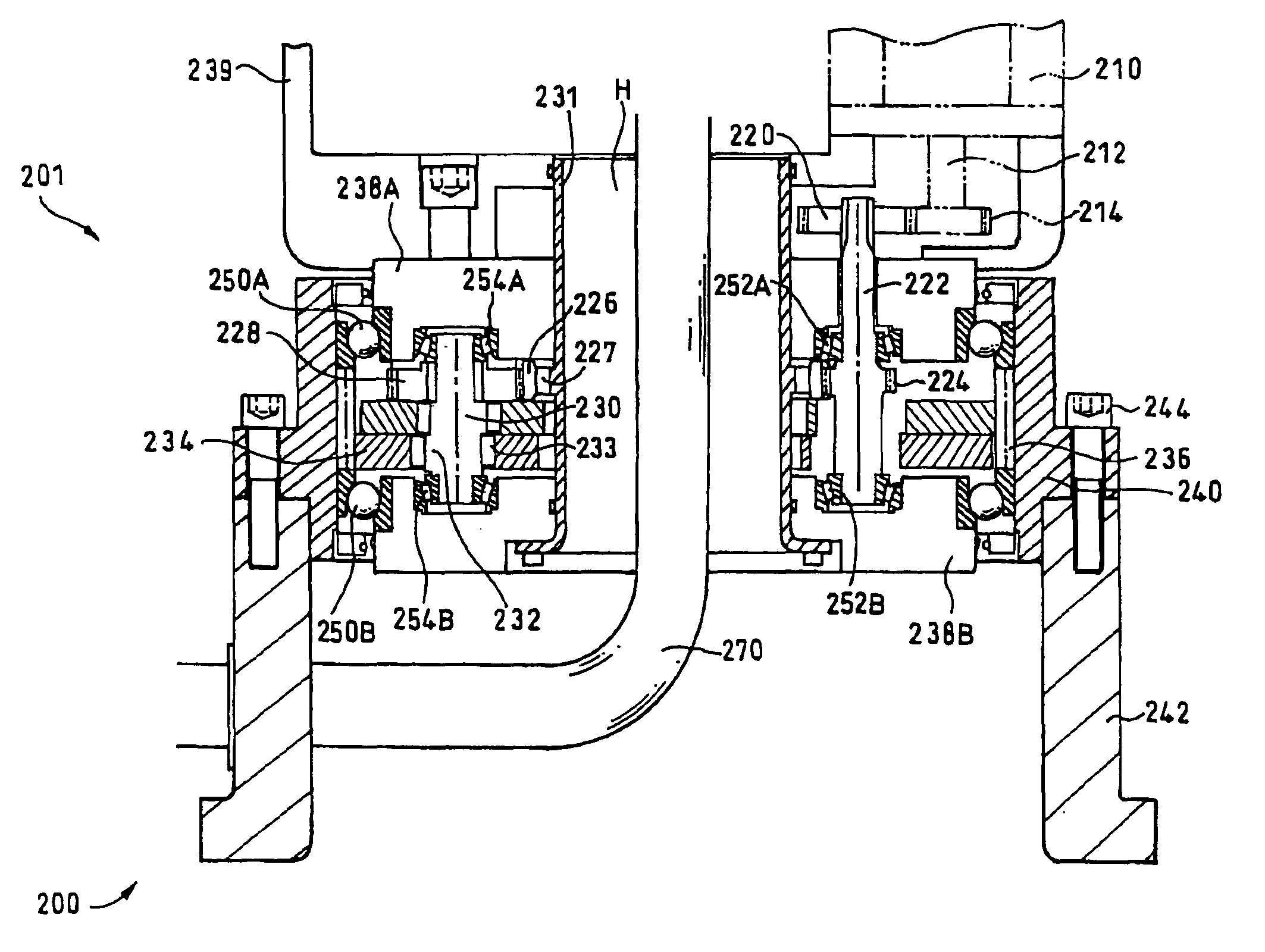
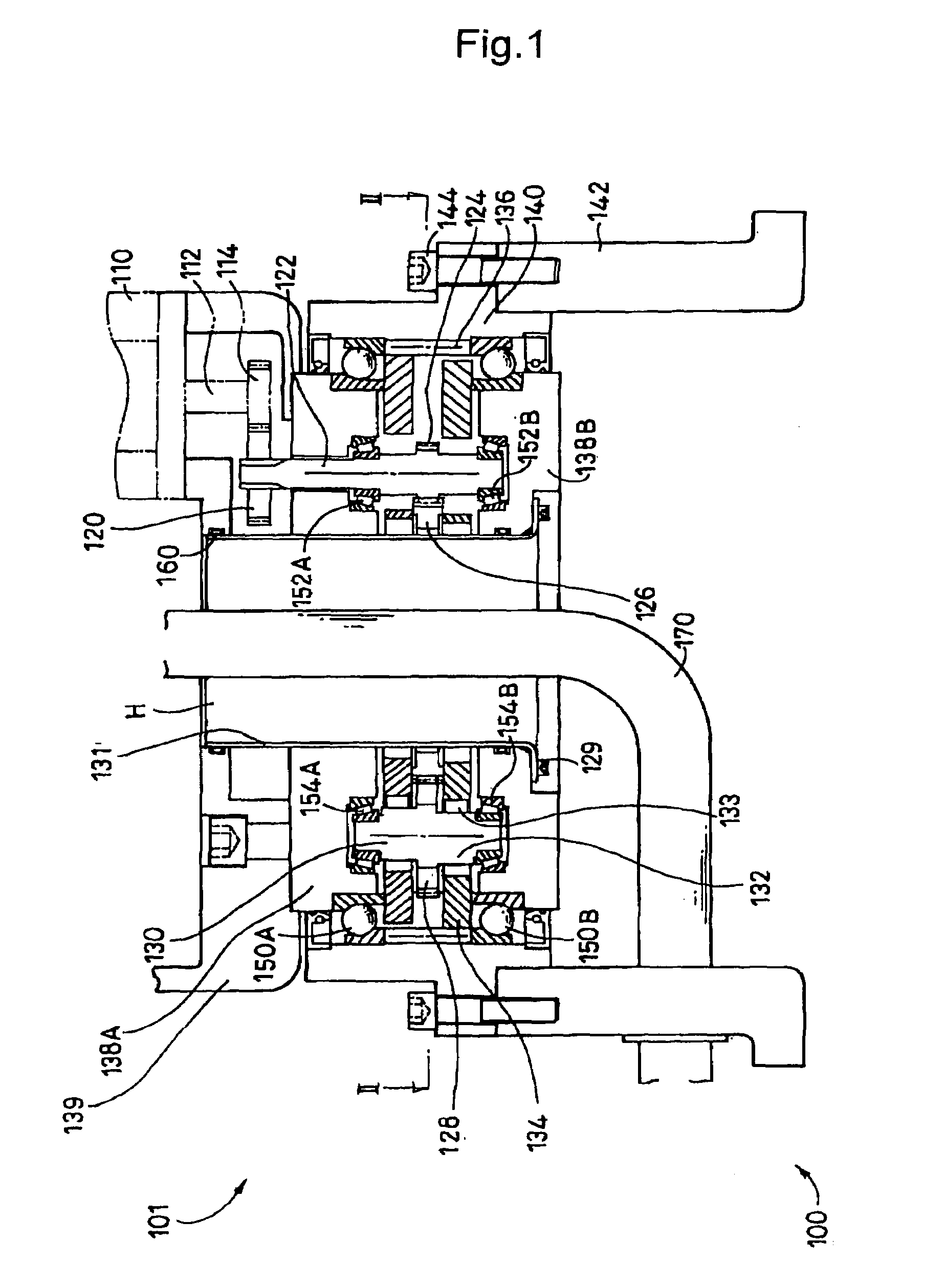
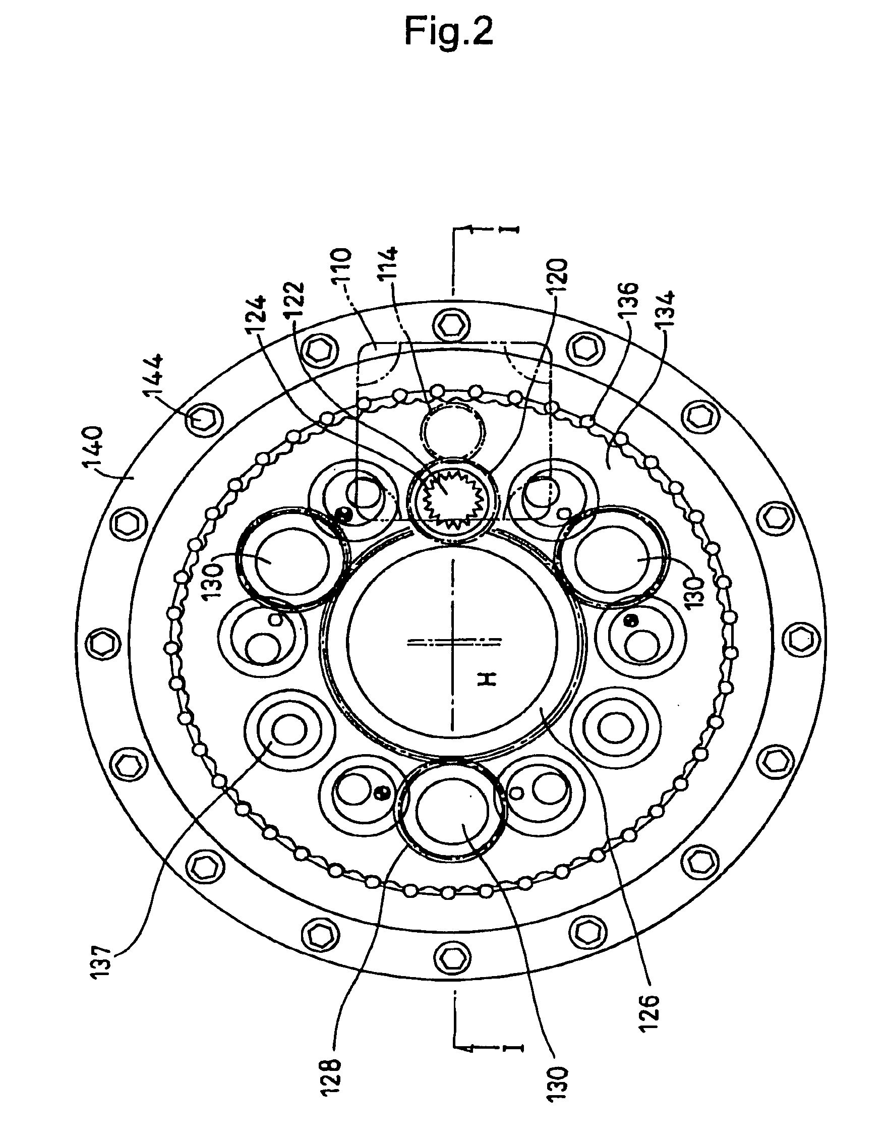
[0026]FIG. 1 is a side cross sectional view of a geared motor 100 according to one of embodiments of the present invention, and FIG. 2 is a cross sectional view taken along line II-II indicated by an arrow in FIG. 1.

[0027]The geared motor 100 includes a motor 110 which serves as a power source and an oscillating internally meshing planetary gear reducer 101. The geared motor 100 is a so-called vertical type geared motor having an axis vertically provided. The motor 110 is provided on an upper surface side of a casing 140 in which a speed reducing mechanism is housed. On the other hand, a base 142 is connected to a lower surface of the casing via a bolt 144. Additionally, a hollow part H is positioned at the center of a radius direction of the geared motor 100, and can be used for running through of a cable or the like.

[0028]The hollow part H is formed alon...


PUM


Abstract

To provide an oscillating internally meshing planetary gear reducer capable of realizing a low cost and a high speed reduction ratio, the oscillating internally meshing type planetary gear reducer is constituted so as to include: an input shaft provided with an input gear which is circumscribed and meshed with a pinion provided on a motor; an input shaft gear formed on the input shaft; a plurality of eccentric body shafts each provided with an eccentric body for oscillating an oscillating external gear; an eccentric body shaft gear which is formed on each eccentric body shaft; and a distributing gear which is meshed with the input shaft gear and the eccentric body shaft gear.

Description

BACKGROUND OF THE INVENTION[0001]1. Field of the Invention[0002]The present invention relates to an oscillating internally meshing planetary gear reducer.[0003]2. Description of the Related Art[0004]Geared motors 1, and 2 and 2′ are conventionally known that are disclosed in Japanese Published Unexamined Patent Application Nos. 2002-106650 and 2002-122190 respectively.[0005]FIG. 6 shows the geared motor 1 disclosed in Japanese Published Unexamined Patent Application No. 2002-106650. FIG. 7 shows the geared motor 2 disclosed in Japanese Published Unexamined Patent Application No. 2002-122190. FIG. 8 shows the geared motor 2′ disclosed in Japanese Published Unexamined Patent Application No. 2002-122190. The same reference symbols are attached to the same or similar parts of each geared motor respectively, and each geared motor will be described.[0006]Each geared motor includes: a motor 10 which serves as a power source; a pinion or pulley 14 provided on a motor shaft 12 of the motor 1...

Claims


Application Information

Patent Timeline
Patent Type & Authority Patents(United States)
IPC IPC(8): F16H1/32
CPCF16H1/32F16H1/00
Inventor HAGA, TAKASHITAMENAGA, JUN
Owner SUMITOMO HEAVY IND LTD
Why Eureka
Try Eureka