

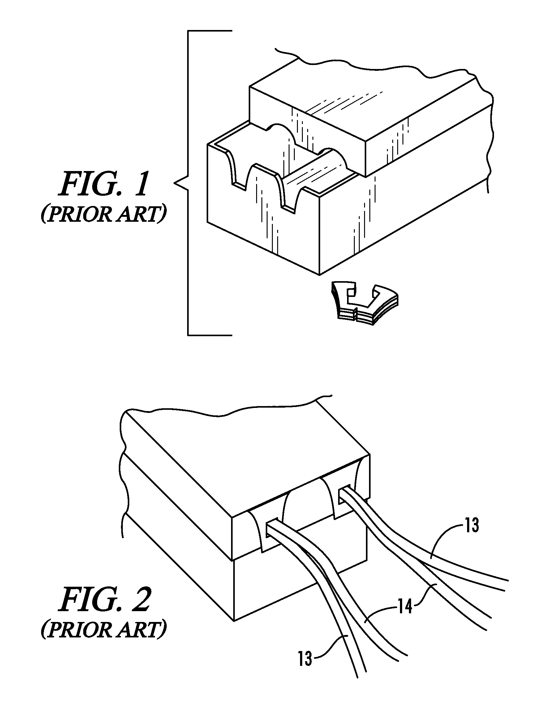
Ballast housing having rolled edge lead wire exit
- Summary
- Abstract
- Description
- Claims
- Application Information
AI Technical Summary
Benefits of technology
Problems solved by technology
Method used
Image

Examples
Embodiment Construction
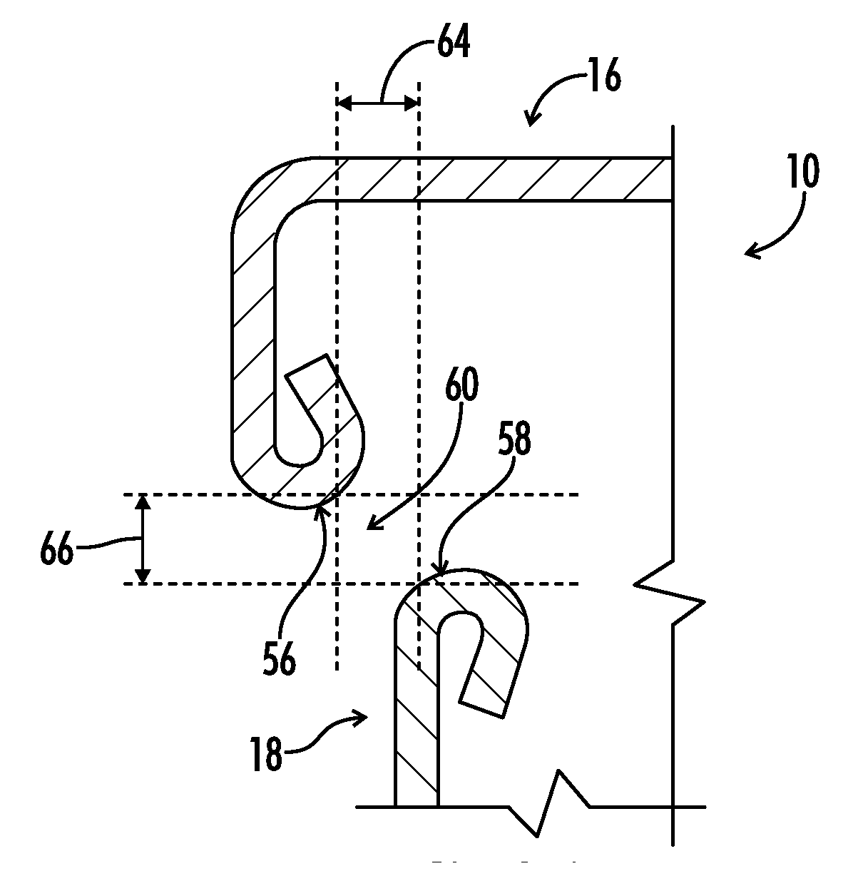
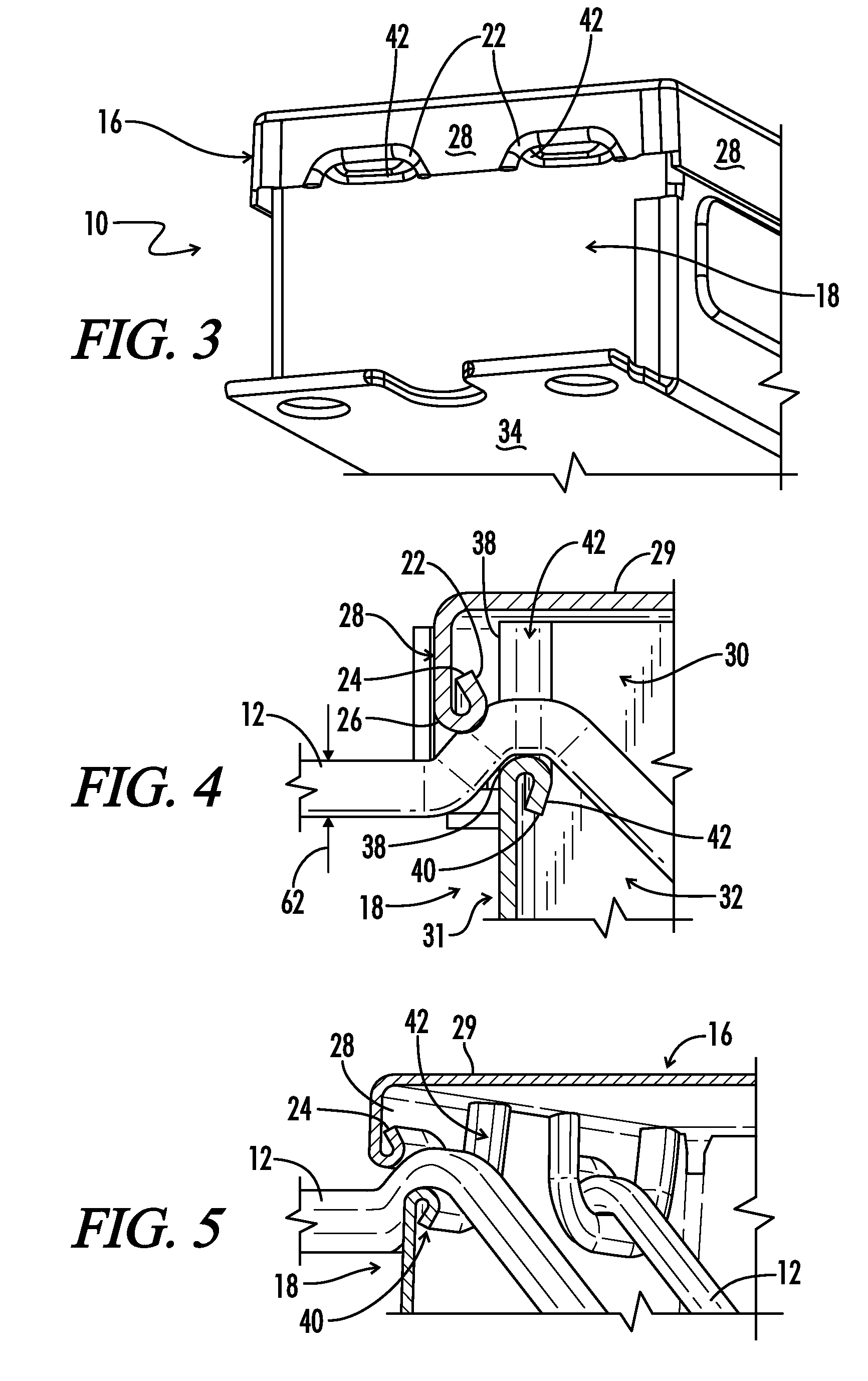
[0040]Referring generally now to the Figures, a ballast housing is shown and generally designated by the numeral 10. The ballast housing can include a wire 12, or wires 13 and 14, extending from the ballast housing 10. The wires 13 and 14 or 12 can be combinations of single or double wires known in the art to extend from electronic devices, such as a ballast 100. The ballast housing 10 includes a lid 16 and a can 18. In one embodiment, shown in FIG. 9A, a ballast housing 10 includes a lead wire opening 60 between the lid 16 and the can 18. The lead wire opening 60 in the housing 10 includes a rolled upper edge 56 and a rolled lower edge 58. The lead wire 12, not shown, passes through the lead wire opening 60 between the rolled upper edge 56 and the rolled lower edge 58. In one embodiment, the rolled upper edge 56 is horizontally misaligned from the rolled lower edge 58 by a horizontal distance 64, as seen in FIG. 9A. The horizontal distance 64 is typically less than the diameter of ...
PUM
 Abstract
Description
Claims
Application Information