Automated detection of problems in software application deployments

a software application and automatic detection technology, applied in the field of software management, can solve problems such as multiple problematic events, reduce the operational efficiency of its staff, and products that do not provide automated analysis of monitored data

Active Publication Date: 2010-08-31
CITRIX SYST INC
View PDF71 Cites 223 Cited by
  • Summary
  • Abstract
  • Description
  • Claims
  • Application Information

AI Technical Summary

Benefits of technology

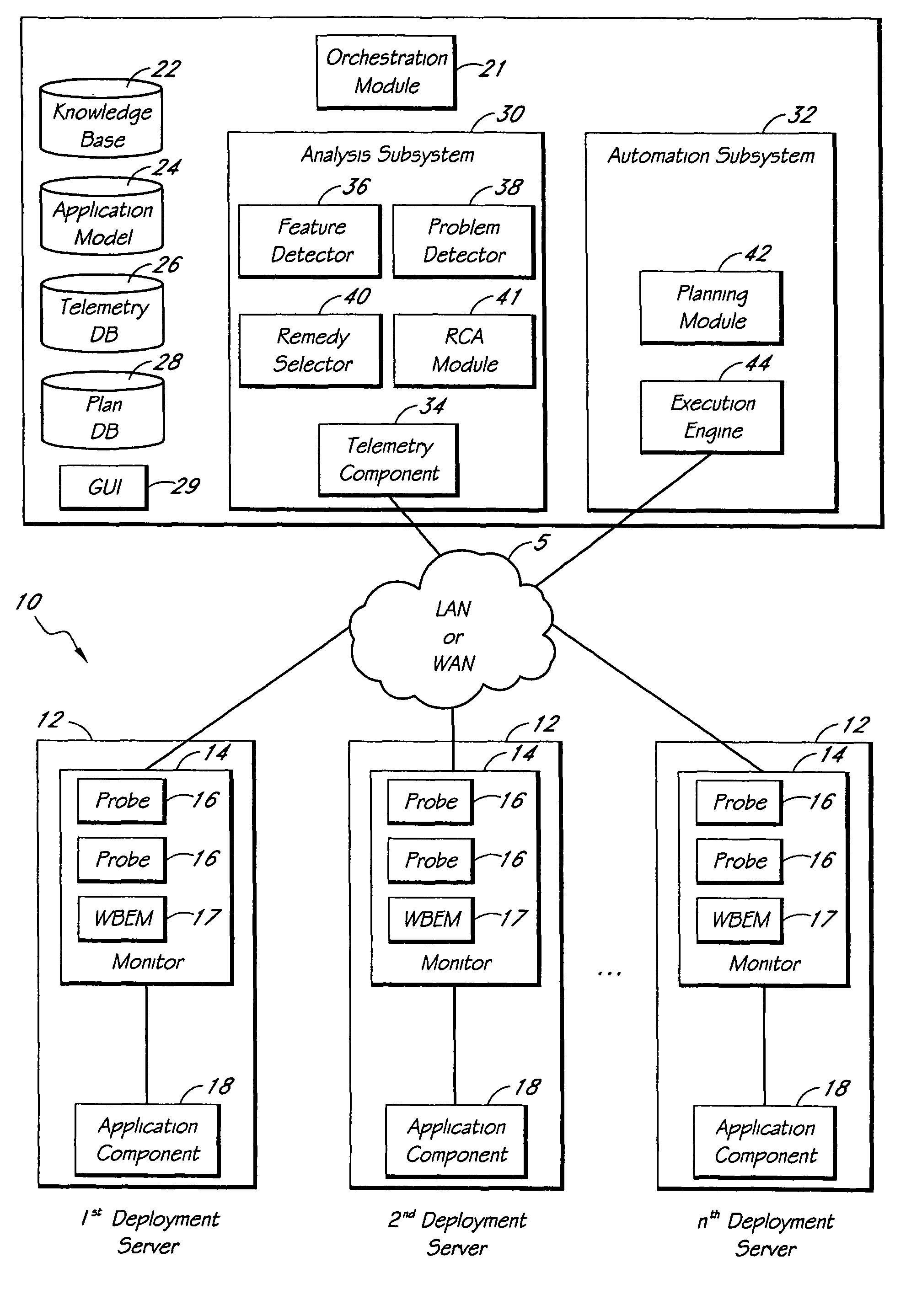
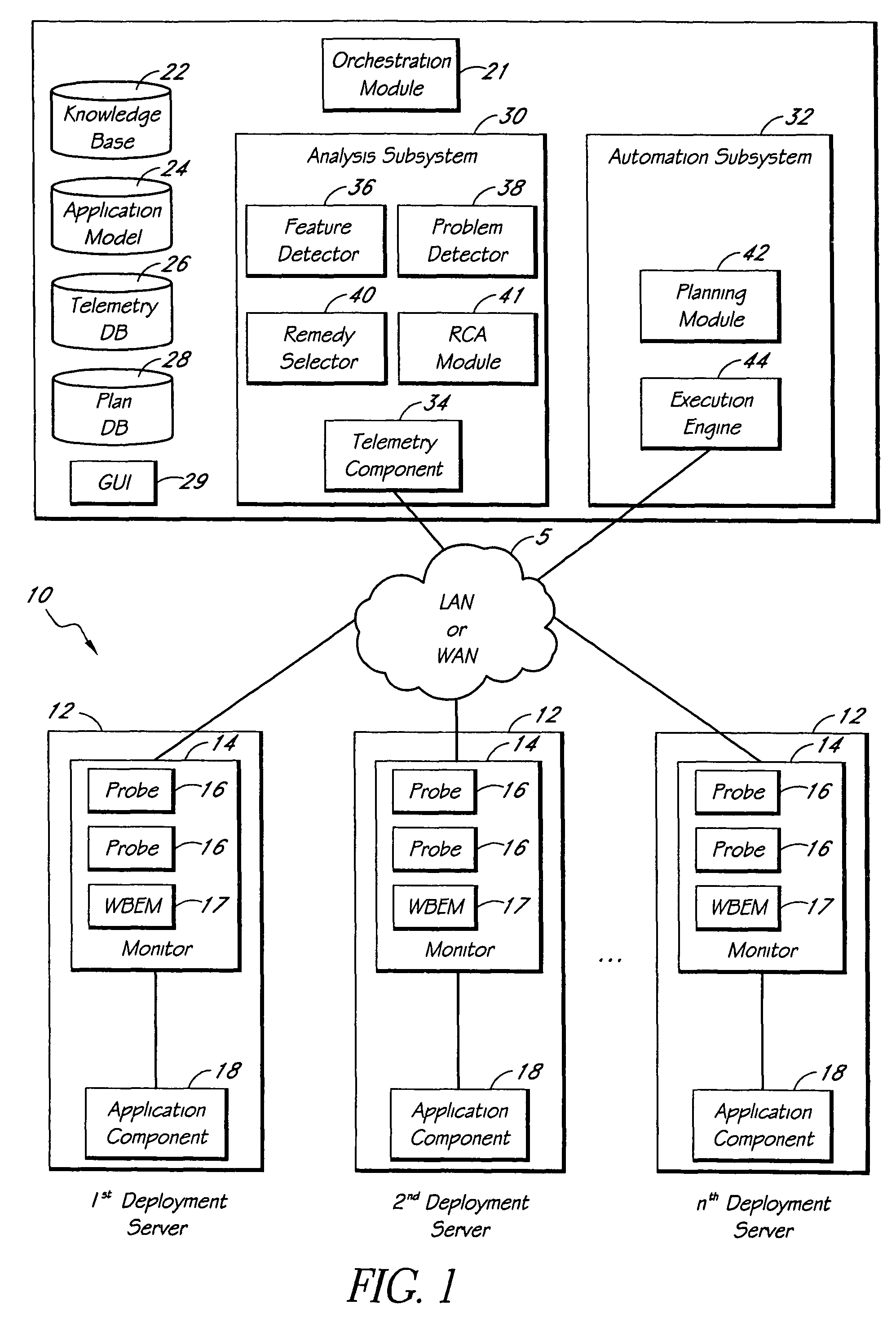
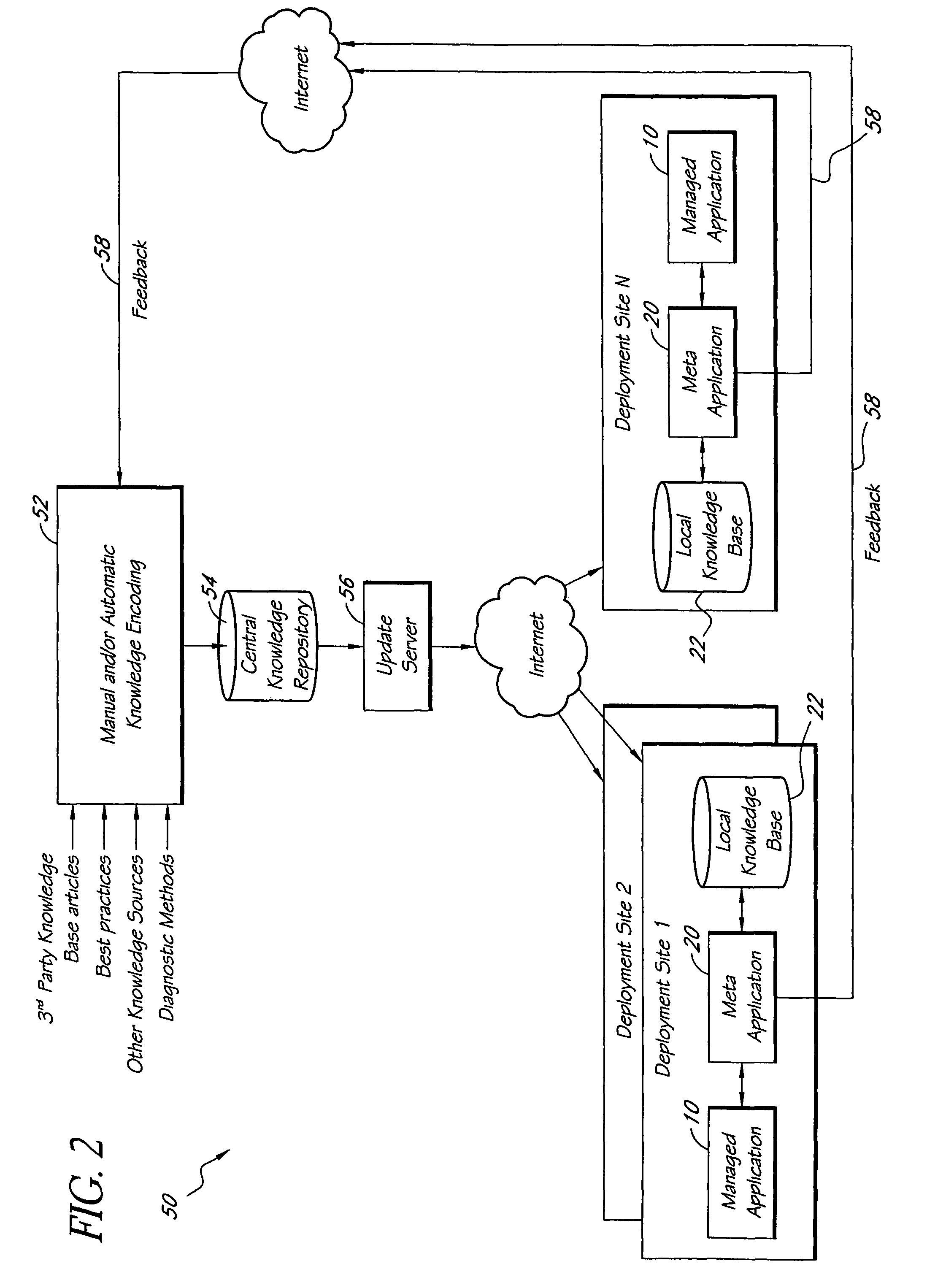
[0011]The meta-application gathers information, or “telemetry,” from the managed application, and uses the telemetry to create mathematical models that describe normal behavior of the managed deployment. The models are used to detect anomalous behavior (which may a type of feature) of the managed deployment, and also to predict possible future problems. The meta-application includes a number of problem detection algorithms, one of which (“Problem Logic”) efficiently maps logical combinations of conditions (e.g., features and deployment state information) to known problems, the conditions comprising declarative knowledge stored in the knowledge base. The meta-application can preferably report problems that are either fully or partially “matched,” along with a confidence level associated with each matched problem. The problem-detection algorithms can advantageously leverage the deployment information compiled in the application model.

Problems solved by technology

These products do not provide any automated analysis of monitored data.
A single problem can result in multiple problematic events.
As a result, IT staff have to manually triage the problems to pinpoint the root-cause problem that caused the set of problems.
It also reduces the operational efficiency of the IT staff, because they have to spend a significant portion of their time troubleshooting the problems.
Also, currently available tools are extremely limited in their ability to continuously optimize a system or alert the IT staff to possible impending failures (for example due to the possible exhaustion of resources), thereby resulting in a limited MTTF.
Therefore, currently available tools have a significant MTTR and limited MTTF, resulting in a relatively low availability A.

Method used


Image

  • Automated detection of problems in software application deployments
  • Automated detection of problems in software application deployments
  • Automated detection of problems in software application deployments

Examples


example

[0514]This section describes an example in which a meta-application 20 uses encoded information extracted from a knowledge base article to diagnose and remedy a particular problem in a deployment 10 of Microsoft Exchange™. FIGS. 22A and 22B together show Microsoft™ Knowledge Base Article ID No. 815759. This particular article describes a problem in which public folder hierarchy messages are stuck in outgoing queues in an Exchange™ 2000 server. The article identifies, under the “SYMPTOMS” heading, two particular warning or information messages that may be logged in the application log. The articles also indicates, under the “CAUSE” heading, that the issue may occur when the “Everyone” group is explicitly denied permissions on both of two listed objects.

[0515]The knowledge base 22 of the meta-application 20 includes a logic rule that describes this problem. The rule includes two inexpensive feature predicates corresponding to the warning log messages, two inexpensive feature predicate...


PUM


Abstract

A system for monitoring and analyzing the operation of a deployment of a software application is disclosed. The system includes a monitoring component, a repository that stores a plurality of rules, and an analysis engine. The monitoring component collects data values of each of a plurality of state metrics associated with the deployment of the software application. At least some of the rules in the repository map respective combinations of states associated with the state metrics to corresponding problems. The analysis engine programmatically detects instances of said problems, at least in-part, by using the rules to analyze the state metric data values collected by the monitoring component. The rules can also include remedies associated with the detected problems, and the system may include remedy selection and execution modules.

Description

CLAIM FOR PRIORITY[0001]This application claims priority under 35 U.S.C. §119(e) to Provisional Application No. 60 / 638,006, filed Dec. 21, 2004, the entire disclosure of which (including appendices) is incorporated by reference herein.BACKGROUND[0002]1. Field[0003]This application relates generally to software management and more specifically to systems and methods for programmatically monitoring and managing deployments of software applications.[0004]2. Description of the Related Art[0005]A variety of commercially available software tools exist for monitoring and providing information about software deployments. These products typically (1) allow a user to statically specify certain aspects about a specific software deployment, (2) monitor those aspects, and (3) alert the user when the monitored aspects cross specified performance thresholds. These products do not provide any automated analysis of monitored data. They are best suited for simple automated monitoring tasks and then p...

Claims


Application Information

Patent Timeline
Patent Type & Authority Patents(United States)
IPC IPC(8): G06F11/00
CPCG06N5/048G06F11/079
Inventor QURESHI, WAHEEDROACH, KELLY BRIANHASSAN, TANVIRMCGINTY, JOHN M.
Owner CITRIX SYST INC
Why Eureka
Try Eureka