Axial motor

a technology of axial motor and axial shaft, which is applied in the direction of dynamo-electric machines, synchronous generators, magnetic circuit shapes/forms/construction, etc., can solve the problems of shortened useful life, unstable power feeing, and complicated structure, so as to reduce leakage flux, simplify power feeding structure, and reduce energy loss

Inactive Publication Date: 2010-09-07
SUMITOMO ELECTRIC IND LTD
View PDF13 Cites 6 Cited by
  • Summary
  • Abstract
  • Description
  • Claims
  • Application Information

AI Technical Summary

Benefits of technology

[0025]As is seen from the above description, according to the present invention, since the field coils and the armature coils are both attached to the stators, a sliding member such as a slip ring is no longer required for the power feeding to the coils. Accordingly, the power feeding structure can be simplified. It is also possible to avoid the problems of shortening in the motor life and instability in the power feeding, which are caused due to contact wear at the slip ring, etc.
[0016]Further, since currents are supplied to the first field coil and the second field coil in opposed directions, magnetic fluxes are also generated in opposed directions by energization of the first field coil and the second field coil. Even with the energization of the two first and second field coils, therefore, the generated magnetic fluxes can be prevented from leaking around both the field coils. Hence, leakage fluxes can be reduced and energy loss can also be reduced.

Problems solved by technology

However, because the field winding 5 is formed as a part of the rotor and power feeding to the field winding 5, which is rotated, has to be performed through the slip ring 9, i.e., the sliding contact, the structure is complicated.
Further, the useful life is shortened due to contact wear of the slip ring 9.
Still another problem is that if the sliding contact at the slip ring 9 is unstable, the power feeing also becomes unstable.

Method used


Image

  • Axial motor
  • Axial motor
  • Axial motor

Examples


Embodiment Construction

[0049]An embodiment of the present invention will be described with reference to the drawings.

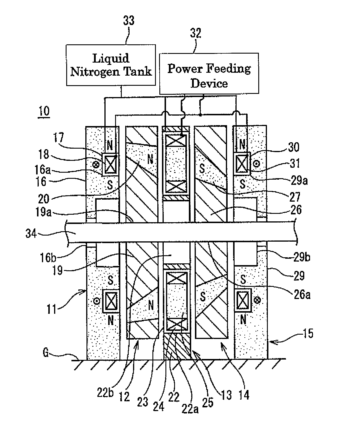
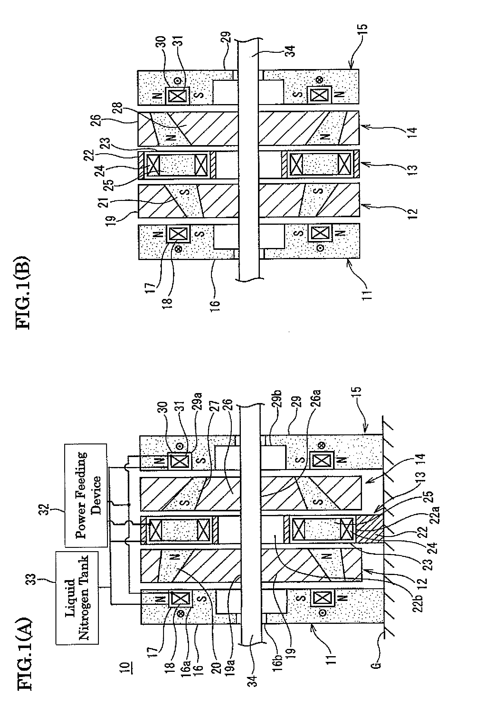
[0050]FIGS. 1 through 6 show the embodiment of the present invention. In an axial motor 10 provided with inductors, a drive shaft 34 penetrates through a first field side stator 11, a first rotor 12, an armature side stator 13, a second rotor 14, and a second field side stator 15 successively in the order named. The first and second field side stators 11, 15 and the armature side stator 13 are each fixed to an installation surface G with a gap left relative to the drive shaft 34. The first and second rotors 12, 14 are externally fitted over and fixed to the drive shaft 34.

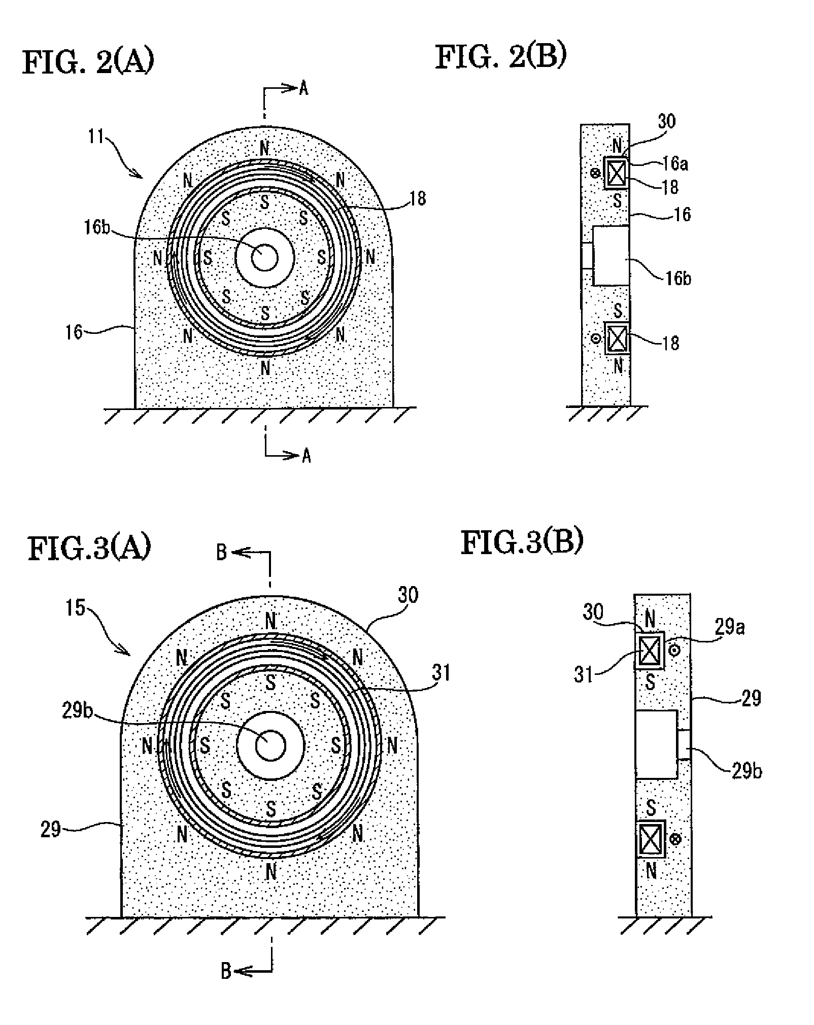
[0051]As shown in FIGS. 2 and 3, the first field side stator 11 and the second field side stator 15 are bilaterally symmetric.

[0052]The first and second field side stators 11, 15 include respectively yokes 16, 29 which are fixed to the installation surface G and are each made of a magnetic material, heat-insulated coolant ...


PUM


Abstract

An axial motor includes an armature side stator (13), a pair of rotors, and a pair of stators, which are arranged with gaps left therebetween in the axial direction of a drive shaft (34). The armature side stator (13) includes armature coils (24). The pair of rotors are a first rotor (12) and a second rotor (14) that are arranged on both sides of the stator (13) and include inducers (20, 21, 27, 28). The pair of stators are a first field side stator (11) and a second field side stator (16) that are arranged respectively on oppositely spacing sides of the first rotor and the second rotor. The first and second rotors (12, 14) are mounted to the drive shaft (34). The first and second field side stators (11, 15) include respectively first and second field coils (18, 31) arranged in a toric form about the axis of the drive shaft (34). The first and second field coils (18, 31) are supplied with currents in opposed directions such that magnetic fluxes are generated in the first and second field coils (18, 31) in opposed directions.

Description

TECHNICAL FIELD[0001]The present invention relates to an axial motor, and more particularly to a motor provided with inductors which are each made of a magnetic material and induce magnetic fluxes on the field magnet side to respective desired positions, the motor having a drive shaft rotated in synchronization with polarity changes of an armature.BACKGROUND ART[0002]In known power generators disclosed in Japanese Unexamined Patent Application Publication No. 54-116610 and No. 6-86517, as shown in FIG. 8, the entirety of a rotor is constructed by penetrating a drive shaft 1 through a bracket 2 serving as an outer casing with bearings 3 interposed therebetween, arranging a field winding 5 around an outer periphery of a yoke 4 which is externally fitted over and fixed to the drive shaft 1, and arranging claw poles 6 and 7 which are alternately projected from the left and right sides of the field winding 5. On the other hand, a stator winding 8 is attached to the bracket 2 in an oppose...

Claims


Application Information

Patent Timeline
Patent Type & Authority Patents(United States)
IPC IPC(8): H02K1/22
CPCH02K19/103H02K19/24H02K55/04H02K1/00H02K1/06
Inventor OKAZAKI, TORUOHASHI, SHINGOSUGIMOTO, HIDEHIKO
Owner SUMITOMO ELECTRIC IND LTD
Why Eureka
Try Eureka