Quasi-coaxial crack feed cavity-backed antenna

A coaxial, cavity-backed technology, used in the field of quasi-coaxial slit-fed cavity-backed antennas, can solve the problems of limited bandwidth, high-frequency end pattern distortion, and easy damage.

Active Publication Date: 2021-08-24
SOUTHWEST CHINA RES INST OF ELECTRONICS EQUIP
View PDF6 Cites 5 Cited by
  • Summary
  • Abstract
  • Description
  • Claims
  • Application Information

AI Technical Summary

Problems solved by technology

[0003] The broadband cavity-backed antenna excited by the bow-tie vibrator is prone to distortion at the high frequency end; the structure of the cavity-backed antenna excited by the open sleeve vibrator is complex, and it is easy to be damaged under high-intensity vibration conditions.
The biggest advantage of the traditional symmetrical vibrator-excited cavity-backed antenna is its simple structure and low cross-polarization level. Its disadvantage is that its own bandwidth is limited, and the standing wave coefficient bandwidth is usually within 1.5:1.
[0004] At the same time, it is prone to pattern distortion at high frequency
Although the existing two-wire balancer has a simple structure and a wide bandwidth, it is limited by the cross-wire connection structure (equivalent distributed inductance) between the positive and negative poles of the vibrator, which limits the high-frequency performance of the antenna (distortion of the pattern and small power capacity )

Method used


Image

  • Quasi-coaxial crack feed cavity-backed antenna
  • Quasi-coaxial crack feed cavity-backed antenna
  • Quasi-coaxial crack feed cavity-backed antenna

Examples


Embodiment 1

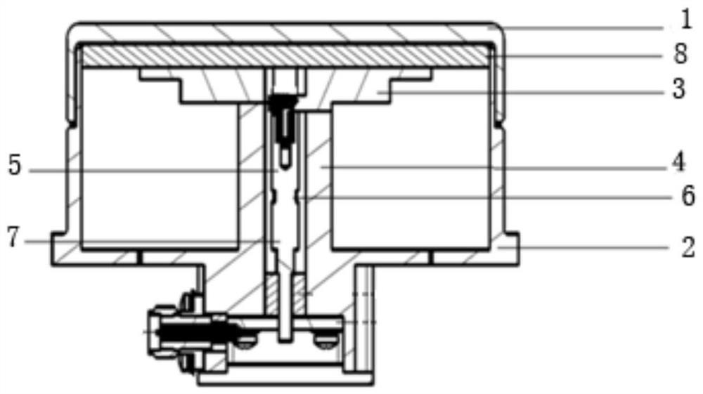
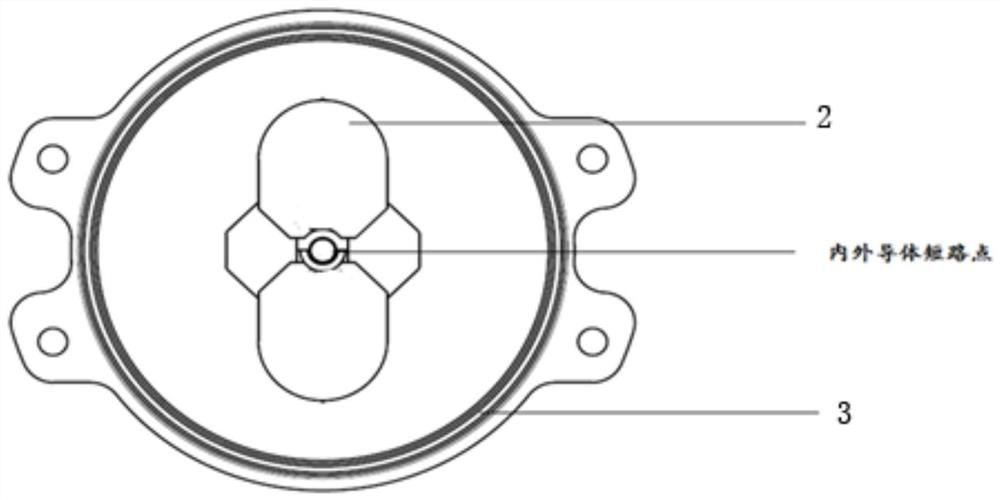
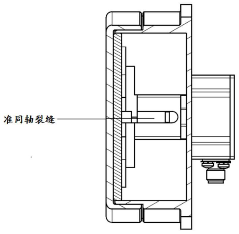
[0038] This embodiment specifically provides a quasi-coaxial slot-fed cavity-backed antenna. Compared with the existing cavity-backed antenna, its improvement lies in expanding The operating bandwidth of the cavity antenna. Its overall structure is as figure 1 As shown, the antenna includes a symmetrical vibrator, an impedance transformer, a dielectric radome, a quasi-coaxial crack balancer, a foam layer, and a reflective back cavity; the dielectric radome is assembled on the reflective back cavity, and the symmetrical vibrator is installed On the quasi-coaxial crack balancer, the impedance transformer is assembled in the crack of the quasi-coaxial crack balancer, and the impedance transformer is also connected to the symmetrical vibrator, and the foam layer is arranged on a symmetrical Between the vibrator and the dielectric radome, it is used to fix the relative distance between the symmetrical vibrator and the dielectric radome.

[0039] In this example, if figure 1As sh...

Embodiment 2

[0050] A quasi-coaxial slot-fed cavity-backed antenna provided in this embodiment has the same design idea and working principle as that of Embodiment 1, and the only difference is that the specific parameters are different. The antenna includes a symmetrical vibrator, an impedance transformer, a dielectric radome, A quasi-coaxial crack balancer, a foam layer and a reflective back cavity; the dielectric radome is assembled on the reflective back cavity, the symmetrical vibrator is mounted on the quasi-coaxial crack balancer, and the impedance converter is assembled on the In the crack of the quasi-coaxial crack balancer, and the impedance transformer is also connected to the symmetrical vibrator, the foam layer shown is arranged between the symmetrical vibrator and the dielectric radome, for fixing the symmetrical vibrator and the dielectric radome the relative distance between them.

[0051] In this example, if figure 1 As shown, the symmetrical vibrator is a stepped structu...

Embodiment 3

[0059] A quasi-coaxial slot-fed cavity-backed antenna provided in this embodiment has the same design idea and working principle as that of Embodiment 1, and the only difference is that the specific parameters are different. The antenna includes a symmetrical vibrator, an impedance transformer, a dielectric radome, A quasi-coaxial crack balancer, a foam layer and a reflective back cavity; the dielectric radome is assembled on the reflective back cavity, the symmetrical vibrator is mounted on the quasi-coaxial crack balancer, and the impedance converter is assembled on the In the crack of the quasi-coaxial crack balancer, and the impedance transformer is also connected to the symmetrical vibrator, the foam layer shown is arranged between the symmetrical vibrator and the dielectric radome, for fixing the symmetrical vibrator and the dielectric radome the relative distance between them.

[0060] In this example, if figure 1 As shown, the symmetrical vibrator is a stepped structu...


PUM


Abstract

The invention relates to the field of cavity-backed antennas, and discloses a quasi-coaxial crack feed cavity-backed antenna which comprises a step structure type symmetrical oscillator, an impedance transformer, a dielectric radome, a quasi-coaxial crack balancer, a foam layer and a circular reflection cavity. The dielectric radome is assembled on the circular reflection cavity, the symmetrical oscillator is assembled on the quasi-coaxial crack balancer, and the foam layer is arranged between the stepped structure type symmetrical oscillator and the dielectric radome and is used for fixing the relative distance between the symmetrical oscillator and the dielectric radome. According to the cavity-backed antenna provided by the invention, a quasi-coaxial crack balanced feed structure is adopted, the advantages of the traditional coaxial crack balanced feed and the double-line balanced feed are combined, and the impedance conversion and the coaxial crack structure are integrated, so that the purposes of eliminating the directional diagram distortion existing in a current popular broadband cavity-backed antenna form, improving the structural reliability and the power capacity under the high-strength condition and enabling the frequency band width to be not smaller than 3: 1 are achieved.

Description

technical field [0001] The invention relates to the field of cavity-backed antennas, in particular to a quasi-coaxial slot-fed cavity-backed antenna. Background technique [0002] Cavity-backed antennas excited by dipoles currently mainly adopt several forms such as symmetrical dipoles, bow-tie dipoles, and open sleeve dipoles. The typical feeding method is two-wire balanced feeding. [0003] The radiation pattern of the broadband cavity-backed antenna excited by the bow-tie oscillator is prone to distortion at the high frequency; the structure of the cavity-backed antenna excited by the open sleeve oscillator is complex, and it is easy to be damaged under high-intensity vibration conditions. The biggest advantage of the traditional symmetrical dipole excitation cavity-backed antenna is its simple structure and low cross-polarization level. Its disadvantage is that its own bandwidth is limited, and the standing wave coefficient bandwidth is usually within 1.5:1. [0004] At...

Claims


Application Information

Patent Timeline
Patent Type & Authority Applications(China)
IPC IPC(8): H01Q13/18H01Q1/50H01Q1/36H01Q15/14H01Q1/42H01Q1/12H01Q5/10H01Q5/335H01Q5/28H01Q5/50
CPCH01Q13/18H01Q1/50H01Q1/36H01Q15/14H01Q1/42H01Q1/12H01Q5/10H01Q5/335H01Q5/28H01Q5/50
Inventor 何清明于伟张琪张杰张永红李智黄迎春林鑫超
Owner SOUTHWEST CHINA RES INST OF ELECTRONICS EQUIP
Why Eureka
Try Eureka