Cloth pulling and feeding mode of cutting machine and cloth pulling and feeding device of cutting machine

A feeding device and cutting machine technology, applied in the direction of spreading thin soft materials, thin material handling, transportation and packaging, etc., can solve the problems of easy deviation, short stroke, inconvenient assembly and maintenance, etc., to achieve easy assembly and maintenance , The feeding structure is simple, and the effect that it is not easy to deviate

Pending Publication Date: 2019-08-16
东莞市超音速智能切割科技有限公司
View PDF6 Cites 7 Cited by
  • Summary
  • Abstract
  • Description
  • Claims
  • Application Information

AI Technical Summary

Problems solved by technology

[0002] In the prior art cutting machine cloth feeding method, the stroke of one feeding is short, the feeding is less, and it is easy to deviate when feeding, and the structure of the cutting machine cloth feeding device used is complicated, which is not easy to assemble and maintain

Method used


Image

  • Cloth pulling and feeding mode of cutting machine and cloth pulling and feeding device of cutting machine
  • Cloth pulling and feeding mode of cutting machine and cloth pulling and feeding device of cutting machine
  • Cloth pulling and feeding mode of cutting machine and cloth pulling and feeding device of cutting machine

Examples


Embodiment 1

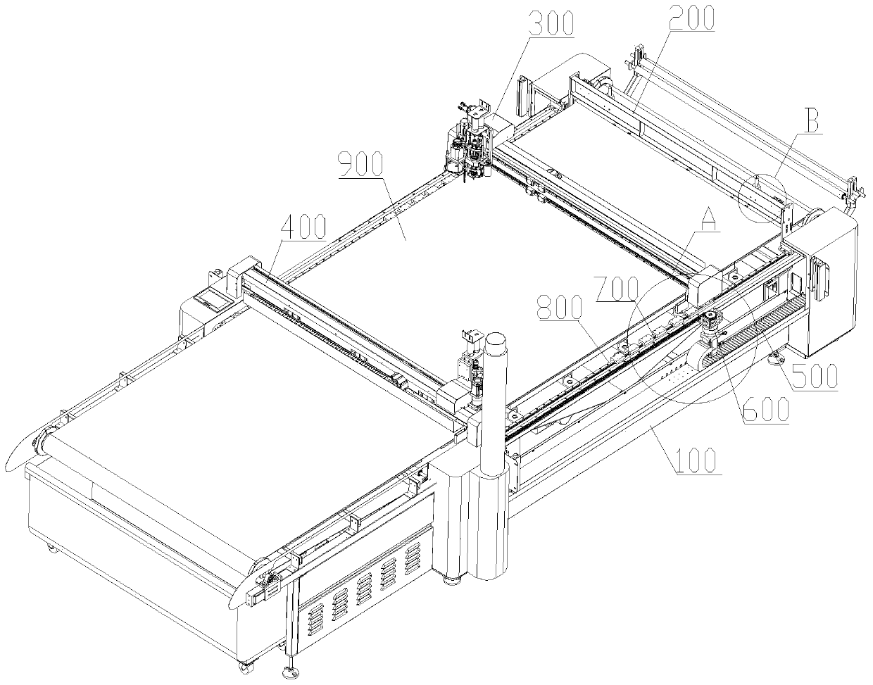
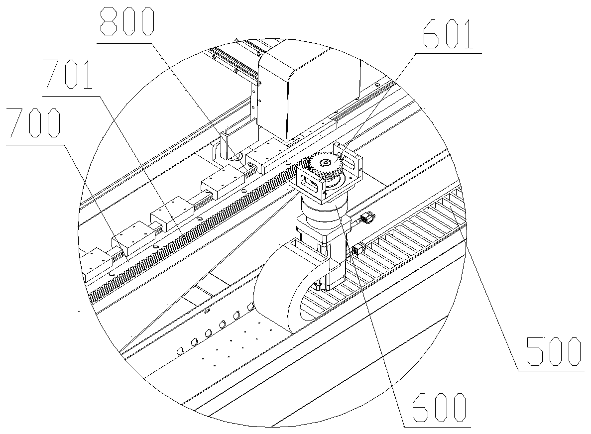
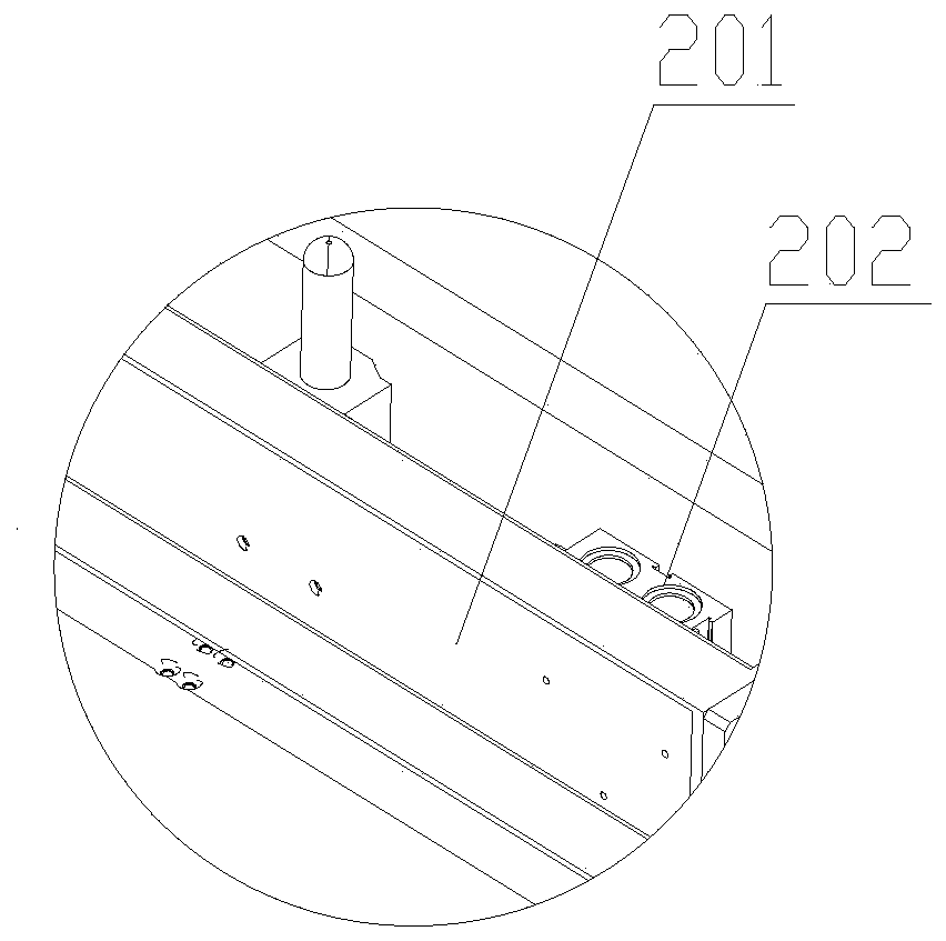
[0024] see Figure 1 to Figure 4 As shown, a cloth feeding device for a cutting machine, the two ends of the frame 100 are respectively provided with a first pressing assembly 200 and a second pressing assembly 400, and the two sides of the frame 100 are respectively provided with a driving assembly 600, and the frame 100 is provided with a slide rail 800, and a slide assembly 700 is provided on the slide rail 800. The slide assembly 700 and the cloth assembly 300 are fixed to each other, and the cloth assembly 300 is located between the first compression assembly 200 and the second compression assembly 400, The driving assembly 600 and the sliding assembly 700 are connected in transmission, and the frame 100 is also provided with tension rollers, which tighten the endless conveyor belt 900 (the tension is appropriate, but not too tight, which will affect the endless conveyor belt 900 being dragged by the magnetic attraction). moving), the endless conveyor belt 900 is located ...


PUM


Abstract

The invention discloses a cloth pulling and feeding mode of a cutting machine and a cloth pulling and feeding device of the cutting machine. According to the cloth pulling and feeding device, a firstpressing component and a second pressing component are arranged at the two ends of a rack correspondingly, a driving component is arranged on the side surface of the rack, a sliding rail is arranged on the rack, a sliding component is arranged on the sliding rail, the sliding component and a cloth pulling component are mutually fixed, the cloth pulling component is positioned between the first pressing component and the second pressing component, the driving component is in transmission connection with the sliding component, a tensioning roller is further arranged on the rack, the tensioning roller is used for tensioning the annular conveying belt, the annular conveying belt is positioned below the first pressing component, the cloth pulling component and the second pressing component, theannular conveying belt is made of a material capable of being magnetically attracted, an electromagnet is arranged at the bottom of the cloth pulling component, the first pressing component, the second pressing component, the driving component, the cloth pulling component and the electromagnet are electrically connected with a controller. The cutting machine has the advantages that the amount ofthe cloth distributed at one time is large and the cloth is not easy to deviate; moreover, the feeding structure is simple, the assembling is convenient, and the maintenance is convenient.

Description

technical field [0001] The invention belongs to the technical field of cutting machines, and in particular relates to a cloth feeding mode of a cutting machine and a cloth feeding device thereof. Background technique [0002] The feeding method of the cutting machine in the prior art has a short feeding stroke and less material, and it is easy to deviate when feeding. The structure of the cloth feeding device of the cutting machine is complicated, and it is not easy to assemble and maintain. Contents of the invention [0003] An object of the present invention is to provide a cloth feeding method for a cutting machine to solve the above technical problems. [0004] Another object of the present invention is to provide a cloth feeding device for a cutting machine to solve the above technical problems. [0005] For reaching this purpose, the present invention adopts following technical scheme: [0006] A cloth feeding device for a cutting machine, the two ends of the frame...

Claims


Application Information

Patent Timeline
Patent Type & Authority Applications(China)
IPC IPC(8): B65H20/16B65H20/10B65H47/00D06H7/00
CPCB65H20/16B65H20/10B65H47/00D06H7/00B65H2701/19
Inventor 邹今令
Owner 东莞市超音速智能切割科技有限公司
Why Eureka
Try Eureka