
Bit error detector for iterative ECC decoder

a decoder and error detector technology, applied in the field of iterative error correction code (ecc) decoders, can solve problems such as reluctance to adopt ldpc codes, data loss, and corruption of read-back signals

Inactive Publication Date: 2010-09-07
SEAGATE TECH LLC
View PDF4 Cites 26 Cited by
  • Summary
  • Abstract
  • Description
  • Claims
  • Application Information

AI Technical Summary

Benefits of technology

This patent describes a way to detect and fix errors in data by grouping them into smaller parts and adding up the results. If there are too many errors, it suggests ways to make things better.

Problems solved by technology

The technical problem addressed in this patent text is the need for a mechanism to monitor the health of the disk surface and detect errors in the data stored on the disk. The current method of using the number of symbols with errors per sector as a metric for monitoring the disk surface is not suitable for iterative ECC decoding, so a new mechanism is needed to produce a similar metric for this purpose.

Method used


Image

  • Bit error detector for iterative ECC decoder
  • Bit error detector for iterative ECC decoder
  • Bit error detector for iterative ECC decoder

Examples


Embodiment Construction

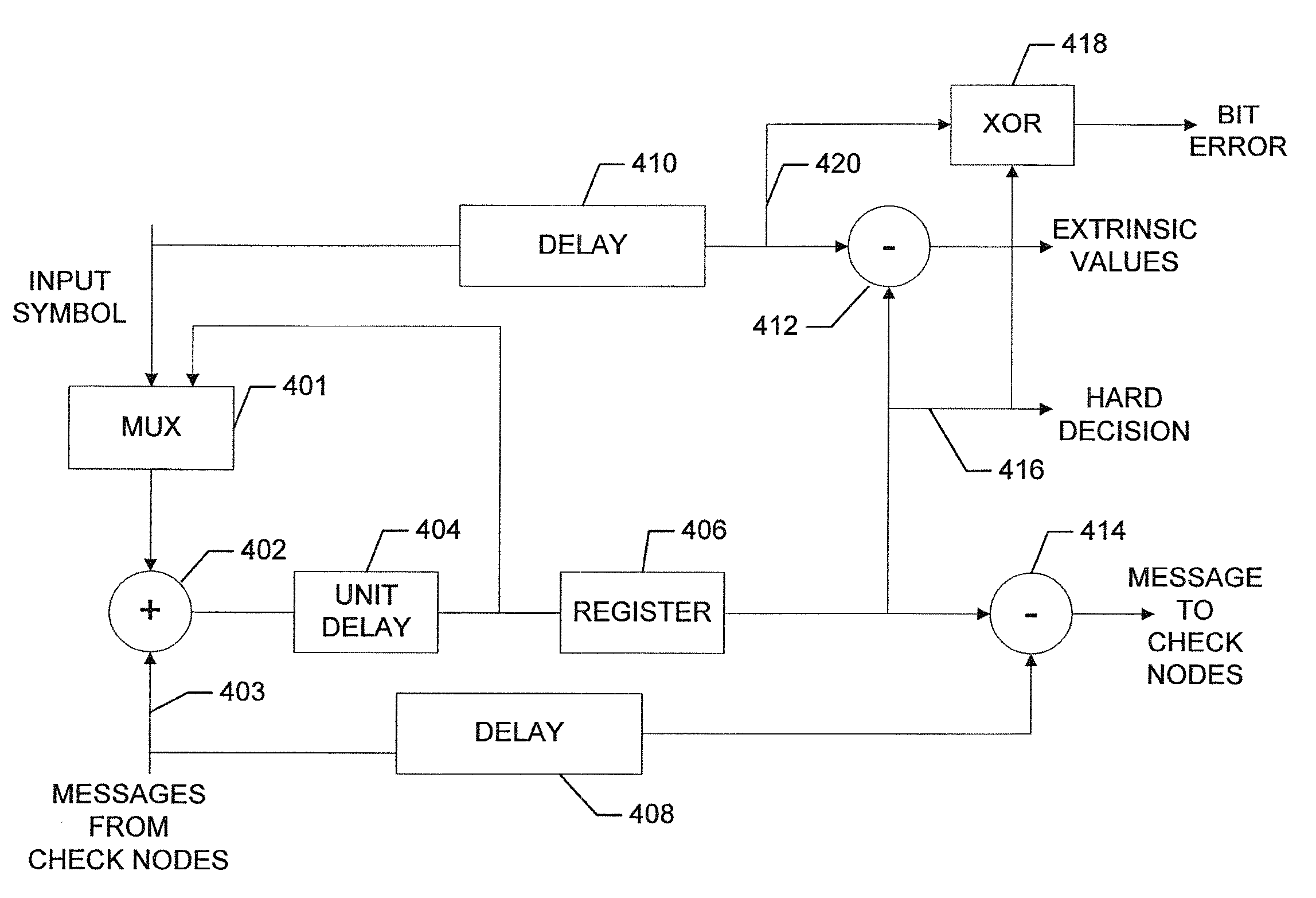
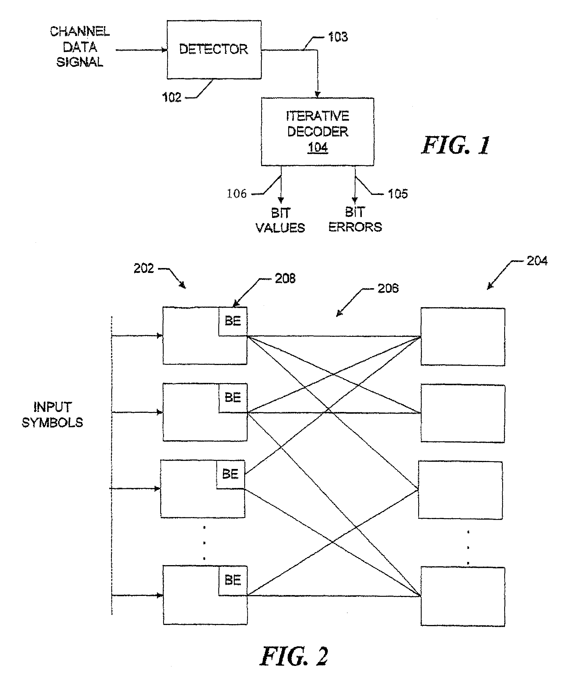
[0021]Referring to FIG. 1, a data signal from a channel is supplied to a channel detector 102, for example, an ISI detector. The detector operating in a known manner detects bits in the data signal and, for each bit, produces an input symbol that consists of a one-bit assigned value, or sign, and multiple bits of associated confidence information. The detector provides the input symbol on line 103 to an iterative decoder 104 which, in the example, is a low-density parity check (LDPC) decoder. The LDPC decoder, which is described in more detail below with reference to FIGS. 2-4, iteratively decodes the input symbols to produce associated hard decision bit values on line 106 and, on line 105, a performance metric that is the number of bit errors per block. Alternatively, the performance metric may be the number of symbols with errors, as discussed in more detail with reference to FIG. 6 below.

[0022]Referring now also to FIG. 2, the LDPC decoder 104 performs message-based iterative dec...


PUM


Abstract

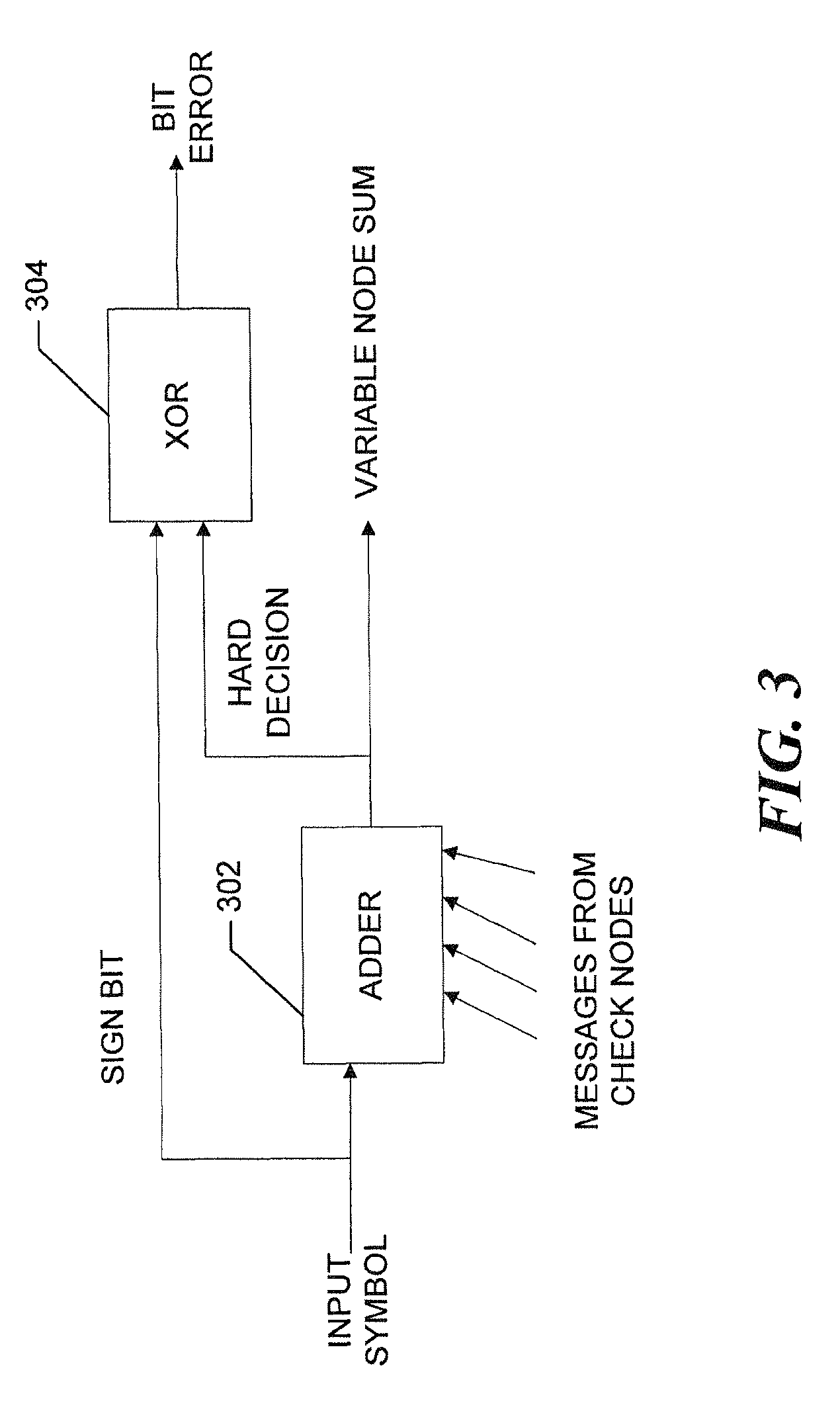
An iterative decoder includes at respective variable nodes, that is, at nodes that correspond to the bits of the code word, bit error detectors that after convergence determine if the respective hard decision bit values have changed from the bit values provided by the channel. The change in value for a given bit indicates that a bit error has been corrected. The bit error detector, for message-passing decoders that perform calculations by addition rather than multiplication, can be readily implemented as an XOR gate. Thus, a bit error is detected at the variable node by XOR'ing the sign bits of the input symbol and the variable node sum. After convergence, the output values produced by the bit error detectors at the respective variable nodes are added together using an adder tree that accumulates the detected bit errors for an entire date block, or ECC code word. Alternatively, the system may group the bits into respective code word symbols and combine the bit error values into symbols-with-errors values using, for example, XOR sub-trees that produce, for each symbol, a single error value. The error value for a given symbol indicates that the symbol is either error-free or includes one or more bit errors, and a total count of the symbols with errors is produced by adding the error values together.

Description


Claims


Application Information

Patent Timeline
Owner SEAGATE TECH LLC
Learn More