Piston cam engine

a technology of piston cam engine and cam shaft, which is applied in the direction of positive displacement engines, piston engine recoilers, machines/engines, etc., can solve the problems of increasing manufacturing costs, difficult to produce internal cam grooves with high precision, and complicated technology, so as to achieve balanced and reliable, reduce noise and vibrations

Inactive Publication Date: 2010-09-14
BAHNEV BOYAN K
View PDF3 Cites 4 Cited by
  • Summary
  • Abstract
  • Description
  • Claims
  • Application Information

AI Technical Summary

Benefits of technology

[0005]The problem solved by the present invention is to provide a piston cam engine which is balanced and reliable, as well as noise and vibrations are decreased.
[0008]In another embodiment of the engine according to the present invention the cross section of each cam section is a line arranged at angle of degrees different from 90° in towards the axes of the cam which arrangement ensuring a reaction having radial component from the cam section when contacting the roller, and the radial component direction is directed to the axes of the cam. This radial component leads to discharge of the arms of followers, because it eliminates a part of the moment caused by the axial component of the same total reaction.

Problems solved by technology

It is a main disadvantage of these engines that the linear guidance of the followers is performed by guide groove which provokes arising of micro strokes in between the contact surfaces of the rollers and the groove when the direction of piston motion has changed.
3D cam is monolithic and it is difficult to produce the internal cam groove with high precision.
All above complicates the technology and increases the manufacturing costs.

Method used


Image

  • Piston cam engine
  • Piston cam engine
  • Piston cam engine

Examples


Embodiment Construction

[0042]According to the invention different two- and one-piston engines could be realized that may afterwards be build in compressors, pumps, internal combustion engines performing different working cycles, as well as internal combustion engines combined with a pump or compressor.

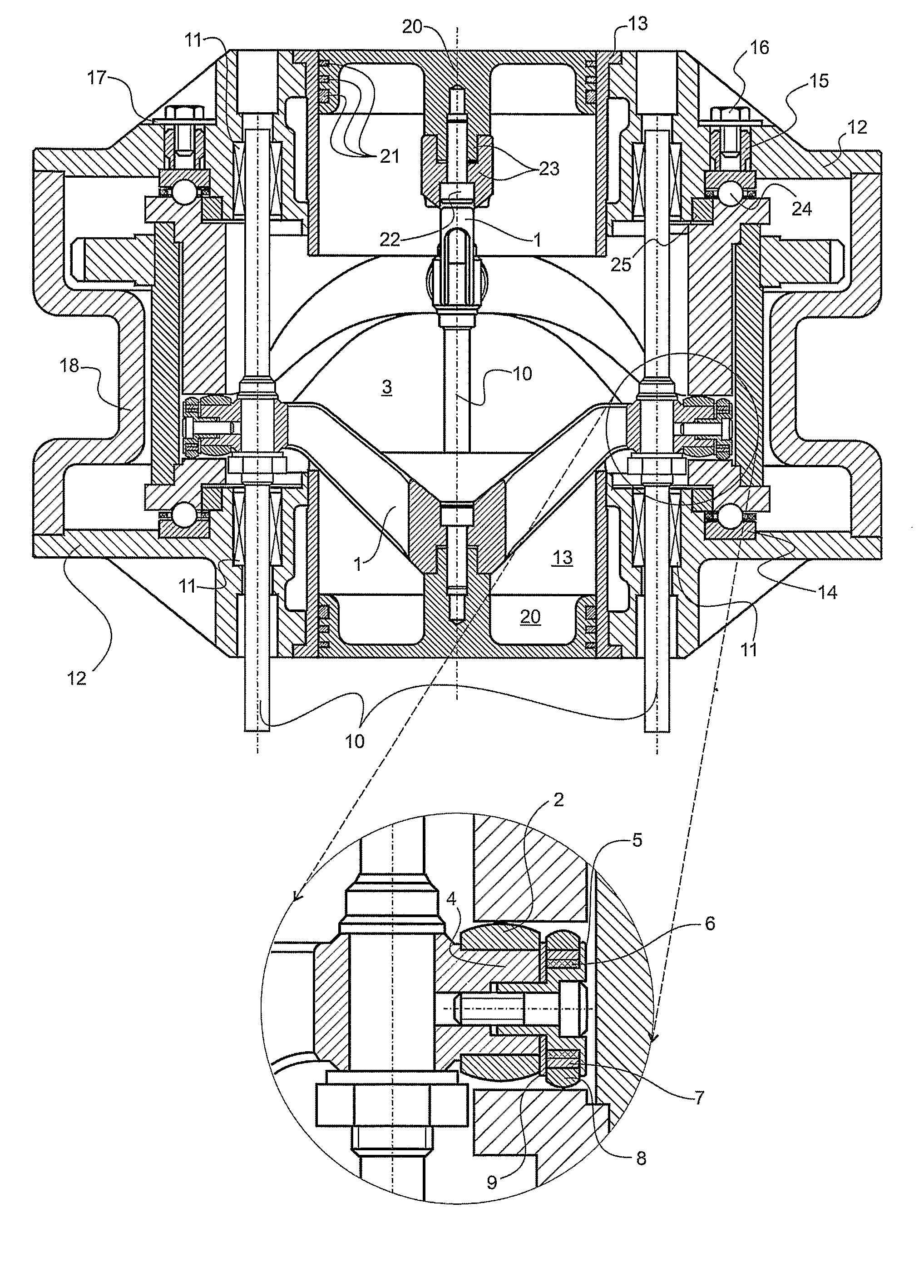
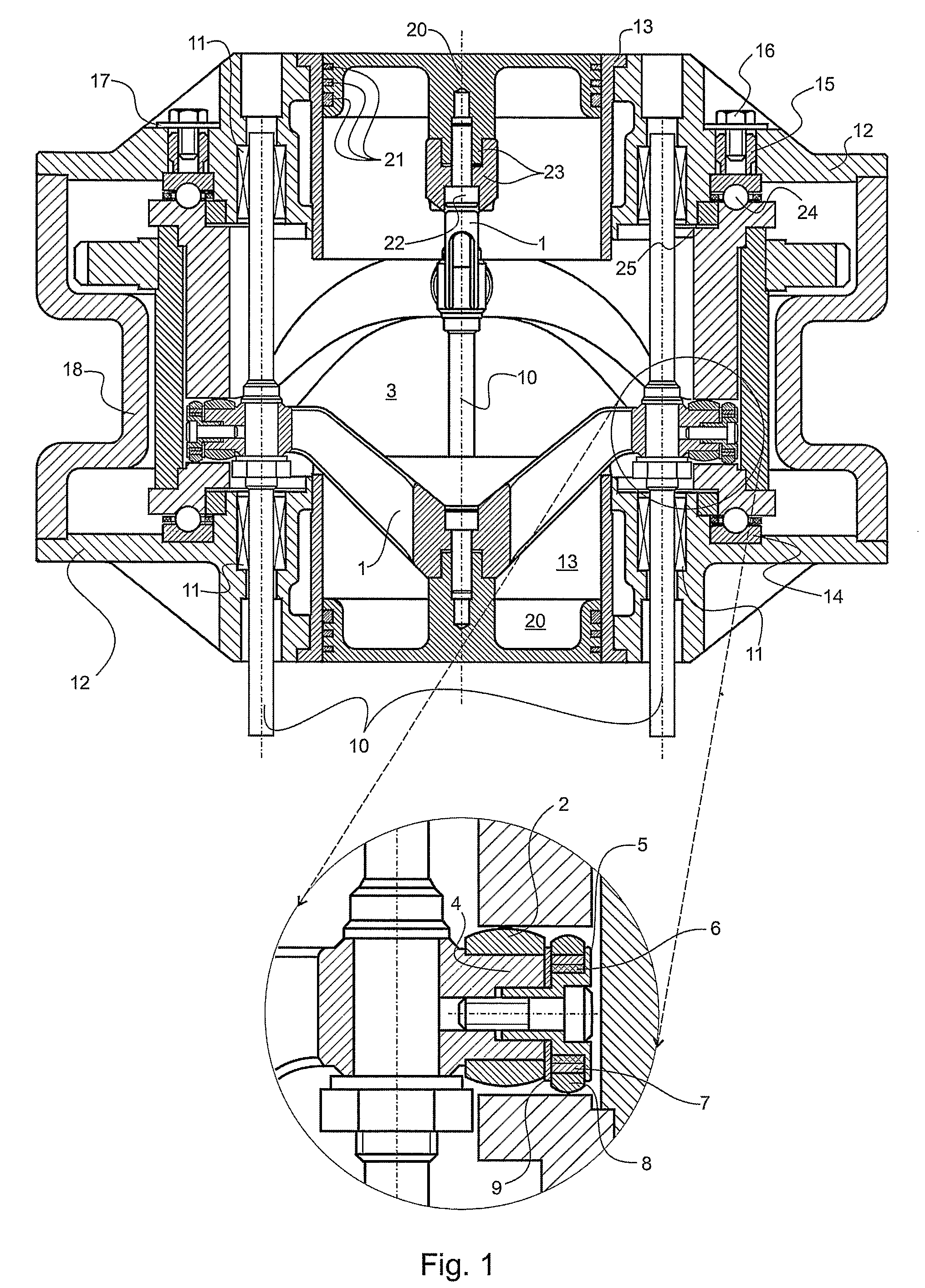
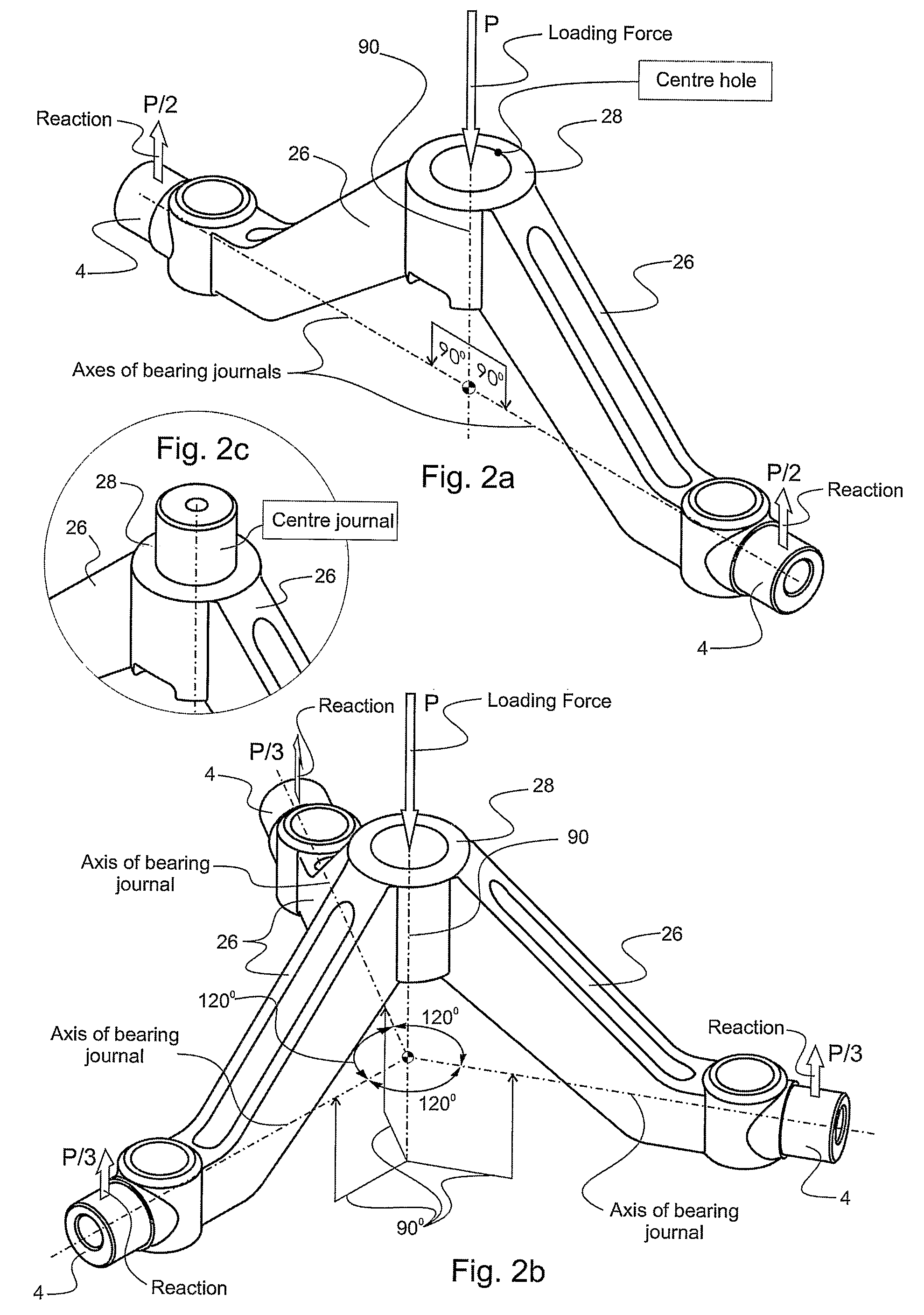
[0043]FIG. 1 shows one preferred embodiment of a two-piston cam engine according to the invention. The engine comprises two followers 1 that are monolithic in that case and each one has two arms 26. To their free endings that are formed as main bearing journals 4, main rollers are mounted 2 that are in contact with their corresponding curved sector of main transformation cam 3. Additional bearing journal 5 is attached to the front part of each main bearing journal 4, on which journal 5 elastic element 6, bush in this case, another bush 7 and additional roller 8 are mounted. The additional roller 8 is in contact with the cam curve that is opposite to cam curve the main rollers 2 are in contact. The axes of ad...


PUM


Abstract

The invention relates to a piston cam engine used in different field of the mechanical engineering, as internal-combustion engines compressors, pumps etc. The cam engine comprises cylinders (13) with pistons (20), a cylindrical tubular 3D cam (3) having a cam groove on the inner cylindrical surface and at least two guides (10) which are guide columns. The cam (3) is composed and includes two coaxial bushes (3a, 3b), each one having corrugated cam section (95a or 95b) from its one side and flange (35) from its other side besides the bushes (3a, 3b) are positioned against each other with its corrugated ends at a distance from each other, and further comprises spacer (37) between the flanges (35) of the bushes (3a, 3b), so as to form the cam groove having a constant section.

Description

FIELD OF THE INVENTION[0001]The invention relates to a piston cam engine and particularly to an opposite piston cam engine, used in different field of the mechanical engineering, as internal-combustion engines, compressors, pumps etc. Engines could be integrated in various land, water and air vehicles, as well as in stationary units.BACKGROUND OF THE INVENTION[0002]The most important and perspective application of opposite piston mechanisms converting the reciprocal linear piston motion into rotation towards output shafts and vice versa is in the field of internal combustion engines.[0003]There are known from DE 3347859, RU 2069273, RU 2073092, RU 2089733, RU 2118472 etc., opposite piston cam engines comprising a housing, a drive or driven shaft, a cylindrical tubular 3D cam having a cam groove on the inner cylindrical surface, opposite coaxial cylinders mounted in the housing, as well as pistons moving in the cylinders and followers having end pieces for moving in the cam groove co...

Claims


Application Information

Patent Timeline
Patent Type & Authority Patents(United States)
IPC IPC(8): F02B75/18
CPCF01B3/04F02B75/26
Inventor BAHNEV, BOYAN KIRILOV
Owner BAHNEV BOYAN K
Why Eureka
Try Eureka