Producer well plugging for in situ combustion processes

a technology of in situ combustion and producer wells, which is applied in the direction of fluid removal, earthwork drilling and mining, borehole/well accessories, etc., to achieve the effect of facilitating the acquisition of products

Active Publication Date: 2010-09-14
CONOCOPHILLIPS CO
View PDF14 Cites 2 Cited by
  • Summary
  • Abstract
  • Description
  • Claims
  • Application Information

AI Technical Summary

Benefits of technology

[0008]According to one embodiment, a method enables performing oil recovery with in situ combustion. The method includes conducting the in situ combustion in a geologic formation, recovering liquid hydrocarbons through a production well during the in situ combustion, and controlling breakthrough of oxidants for the in situ combustion into the production well at locations along the production well where a flow path for the oxidants bypasses a combustion front of the in situ combustion. An operation performed during the in situ combustion provides the controlling that is independent of naturally occurring processes during the in situ combustion.
[0009]For one embodiment, a method of performing oil recovery with in situ combustion includes injecting oxidant into an injection well to establish a combustion front of ignited oil within a geologic formation. Propagation of the combustion front through the formation facilitates obtaining products. The products flow through a production well having first and second portions that permit inflow of the products from the formation into the production well. The method further includes obstructing the inflow through the first portion of the production well with a blockage conveyed from surface into the production well, wherein inflow of the products through the second portion occurs after obstructing the first portion.

Problems solved by technology

In addition, the method includes operating a device disposed within the production well to create an obstruction to the inflow at the first portion while leaving a second portion of the production well open to the inflow of the products.

Method used


Image

  • Producer well plugging for in situ combustion processes
  • Producer well plugging for in situ combustion processes
  • Producer well plugging for in situ combustion processes

Examples


Embodiment Construction

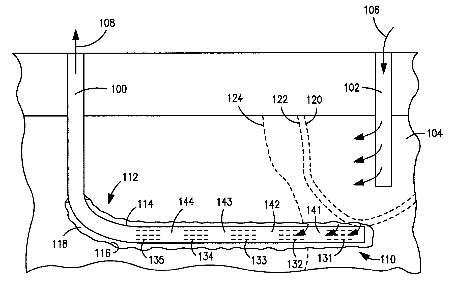
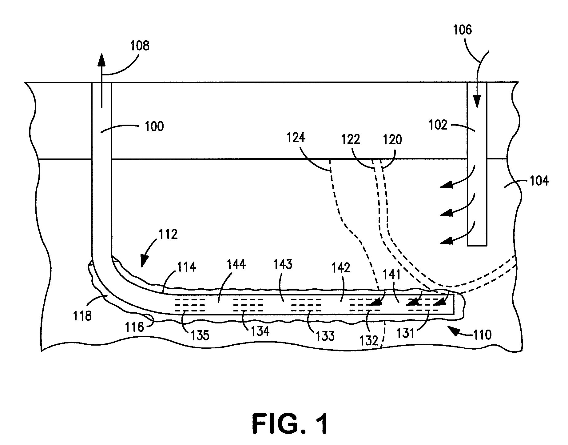
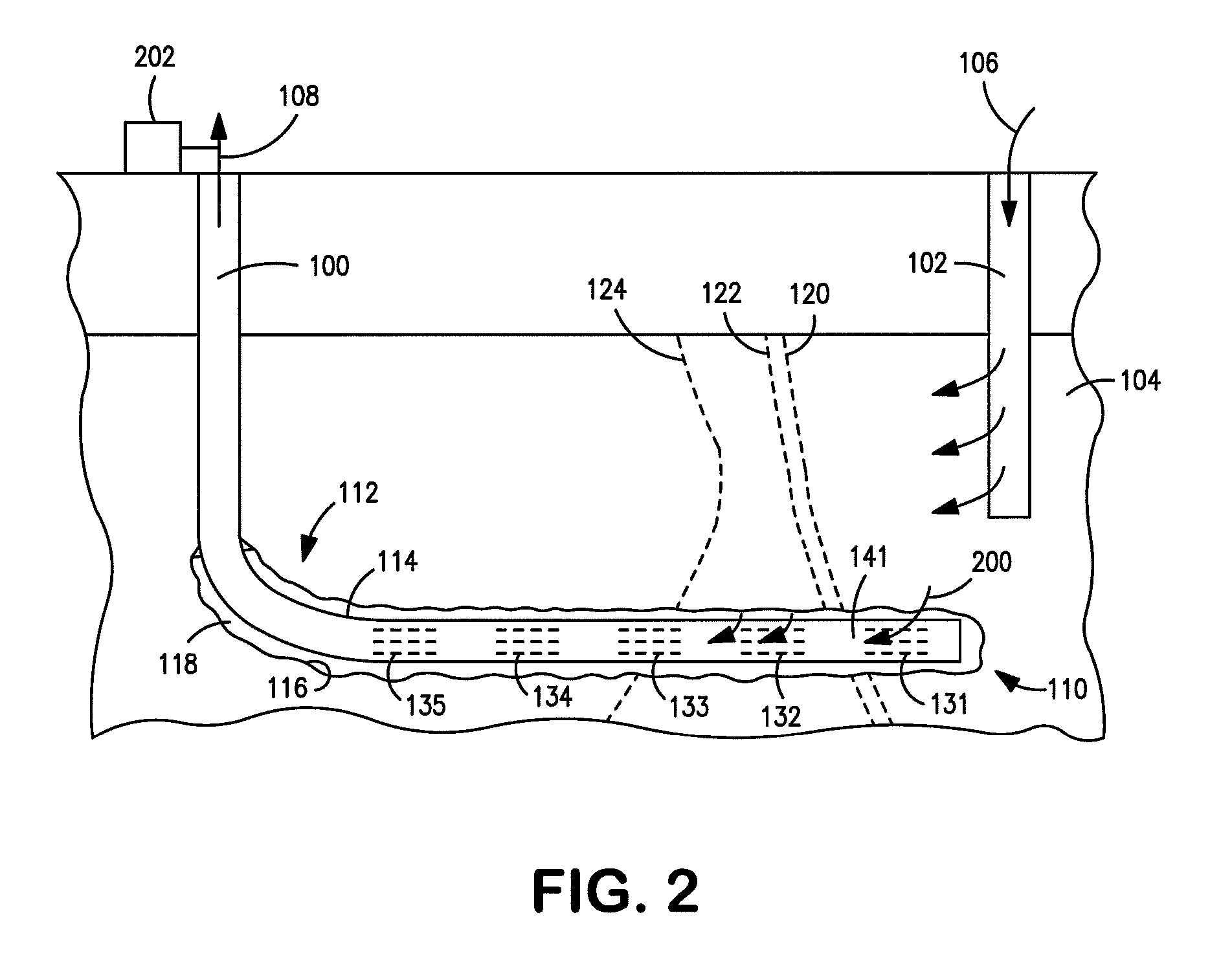
[0015]Embodiments of the invention relate to controlling location of inflow into a production well during oil recovery with in situ combustion. The production well includes longitudinal intervals closable to the inflow at different identified times. Once a combustion front from the in situ combustion comes into proximity with one of the intervals or passes one of the intervals, a blockage conveyed from surface into the production well forms a barrier to the inflow at the interval that has come into proximity with, or been passed by, the combustion front. An example of the blockage includes a cement plug delivered through coiled tubing into the production well, which may include production tubing that defines the intervals based on at least two consecutive alternating lengths of solid wall sections and slotted or perforated sections of the production tubing.

[0016]FIG. 1 illustrates a production well 100 and an injection well 102 that are each defined by boreholes drilled to intersect...


PUM


Abstract

Methods and apparatus relate to controlling location of inflow into a production well during in situ combustion. The production well includes intervals closable to the inflow at identified times. Once a combustion front from the in situ combustion passes one of the intervals, a blockage conveyed from surface into the production well forms a barrier to the inflow at the interval that has been passed by the combustion front. An example of the blockage includes a cement plug delivered through coiled tubing into the production well, which may include production tubing that defines the intervals based on at least two consecutive alternating lengths of solid wall sections and slotted or perforated sections of the production tubing.

Description

CROSS-REFERENCE TO RELATED APPLICATIONS[0001]NoneSTATEMENT REGARDING FEDERALLY SPONSORED RESEARCH OR DEVELOPMENT[0002]NoneFIELD OF THE INVENTION[0003]Embodiments of the invention relate to methods and systems for oil recovery with in situ combustion.BACKGROUND OF THE INVENTION[0004]In situ combustion offers one approach for recovering oil from reservoirs in certain geologic formations. With in situ combustion, an oxidant injected into the reservoir reacts with some of the oil to propagate a combustion front through the reservoir. This process heats the oil ahead of the combustion front. Further, the injection gas and combustion gas products drive the oil that is heated toward an adjacent production well.[0005]Success of in situ combustion depends on stability of the combustion front. For maximum recovery of the oil, the combustion front must be able to stay ignited in order to sweep across the entire reservoir above a horizontal portion of the production well. Prior approaches often...

Claims


Application Information

Patent Timeline
Patent Type & Authority Patents(United States)
IPC IPC(8): E21B43/243
CPCE21B43/243
Inventor DREHER, JR., WAYNE REIDMENARD, WENDELL PETER
Owner CONOCOPHILLIPS CO
Why Eureka
Try Eureka